Hoisting and Rigging
Fundamentals
for
Riaaers
and ODerators
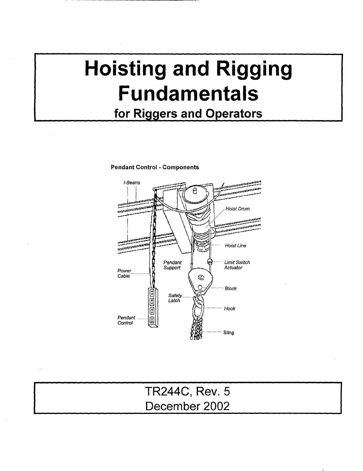
Pendant Control
-
Components
TR244C,
Rev.
5
December
2002
TR244C
Rev
.
5
TABLE
OF
CONTENTS
INTRODUCTION
............................................................
ii
HOISTING AND RIGGING OBJECTIVES
.........................................
1
WIRE ROPE SLINGS .........................................................
2
SYNTHETIC WEBBING SLINGS ...............................................
IO
CHAINSLINGS
............................................................
14
METAL MESH SLINGS
......................................................
18
SPREADER BEAMS
........................................................
19
RIGGING HARDWARE
......................................................
22
INSPECTION TAG
..........................................................
39
CRITICAL
LIFTS
...........................................................
40
GENERAL HOISTING AND RIGGING PRACTICES ................................
44
HANDSIGNALS
............................................................
64
INCIDENTAL HOISTING OPERATOR OBJECTIVES
............................... 68
HOISTS
..................................................................
69
OVERHEAD AND GANTRY CRANES
...........................................
71
MOBILECRANES
..........................................................
77
APPENDIX
................................................................
81
TC:0007224.01
i
TR244C
Rev.
5
INTRODUCTION
HOISTING AND RIGGING PROGRAM
Safety
should be the
first priority
when
performing lifting operations. An
understanding
of
the capabilities and
limitations of the equipment will support this.
The safety policy
“lf
It‘s Not Safe, Don‘t
Do
It”
is important not only for
your
safety, but
the safety
of
your coworkers.
The material outlined in this manual outlines
the requirements
of the DOE Hoisting and
Rigging program.
It
requires persons who
perform rigging or operate hoisting
equipment
to be trained to ensure that
the
personnel are competent to perform the
operation. The
qualification
is for a period
the
three years.
The training requires a
written exam and practical demonstration.
The requirements for
operator training and
qualification
can be reviewed
in
the
DOE
Hoisting
and
Rigging
Manual.
TC:0007224.01
TR244C
Rev.
5
HOISTING AND RIGGING OBJECTIVES
KNOWLEDGE OBJECTIVES
Explain the qualification requirements
of
the Rigging Training Program.
Demonstrate how to calculate the load
on the sling using the load angle factor
for various load angles.
Explain the proper use and limitations of
the various rigging equipment and
hardware (wire rope, synthetic web
slings, shackles, eyebolts, hooks, etc.).
Identify the components and describe
the characteristics
of
wire rope and
synthetic slings.
Describe and state what an ordinary lift
and critical
lift
is.
Explain the responsibilities of the
Person-ln-Charge
(PIC)
and designated
leader.
Explain safe working practices to
consider when performing hoisting and
rigging.
State the requirements for routine and
periodic inspections.
State the proper hand signals used
during lifting operations.
TC:0007224.0
1
Page
1
of
86
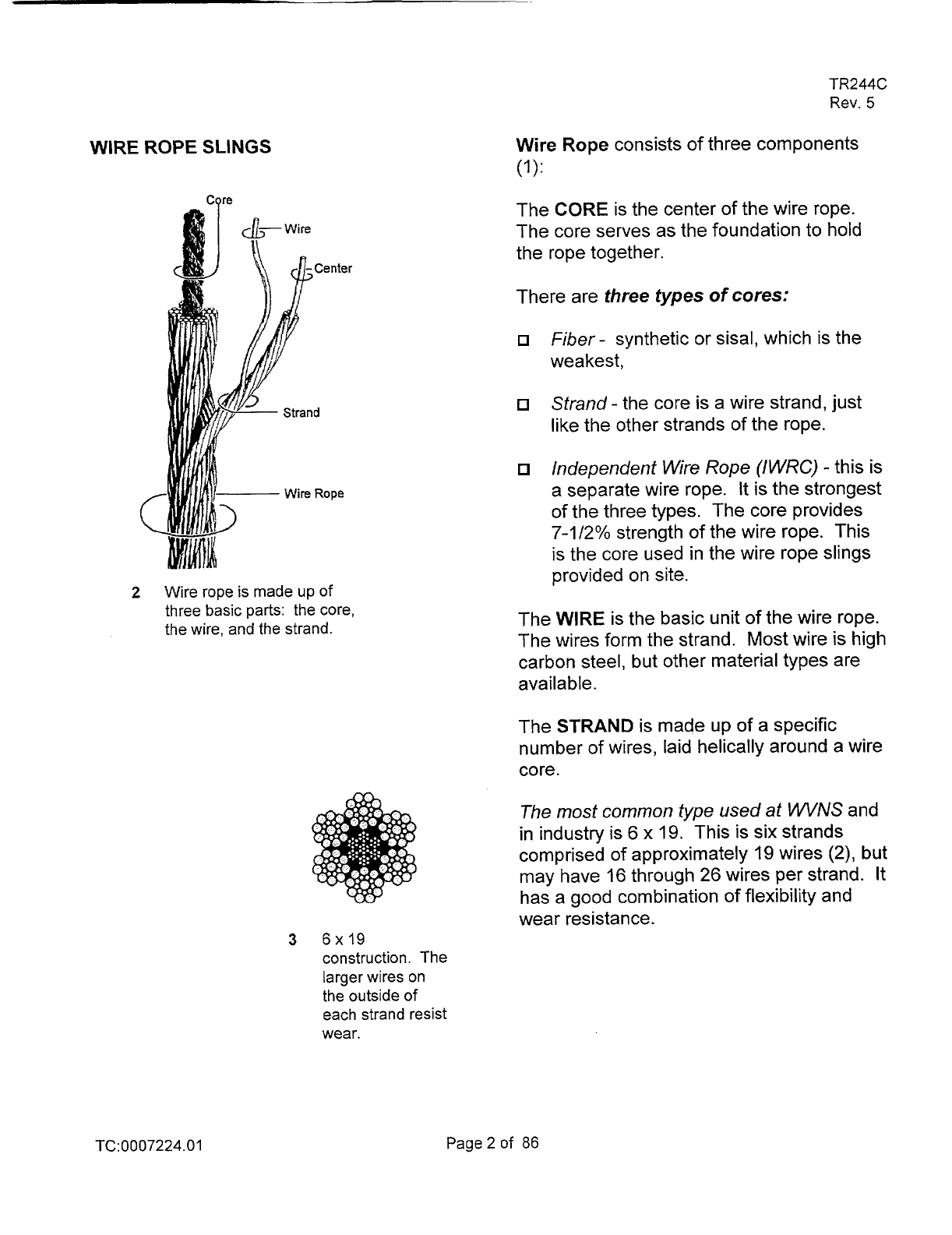
2
WIRE ROPE
SLINGS
Cqre
Wire rope is made up
of
three basic parts: the core,
the wire, and the strand.
3
6x19
construction. The
larger wires on
the outside of
each strand resist
wear.
TR244C
Rev.
5
Wire Rope consists of three components
(1):
The CORE is the center
of
the wire rope.
The core serves as the foundation to hold
the rope together.
There are
three types
of
cores:
Fiber
-
synthetic
or
sisal, which is the
weakest,
Strand
-
the core is a wire strand, just
like the other strands
of the rope.
Mependent
Wire Rope
(IWRC)
-this is
a separate wire rope. It is the strongest
of the three types. The core provides
7-1/2%
strength of the wire rope. This
is the core used in the wire rope slings
provided on site.
The WIRE is the basic unit
of
the wire rope.
The wires form the strand. Most wire
is
high
carbon steel, but other material types are
available
.
The
STRAND
is made up
of
a specific
number of wires, laid helically around a wire
core.
The
most
common
type
used
at
WVNS and
in industry is 6
x
19. This is six strands
comprised
of
approximately 19 wires (2), but
may have 16 through 26 wires per strand. It
has a good combination
of flexibility and
wear resistance.
TC:0007224.01
Page2of
86
5
Right
by.
Regular
Lay
Rghl
Lay.
Lang
Lay
Let7
Lay
-
RegLbrby
4
6
TR244C
Rev.
5
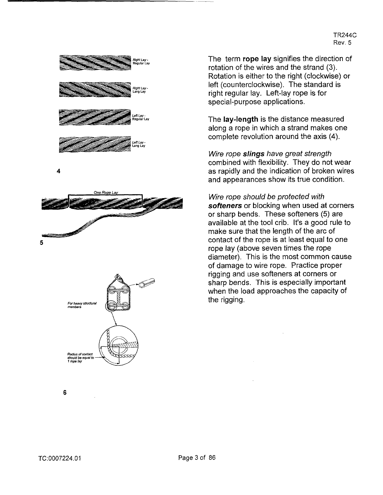
The term
rope
lay
signifies the direction
of
rotation of the wires and the strand
(3).
Rotation is either to the right (clockwise) or
left (counterclockwise). The standard is
right regular lay. Left-lay rope is for
special-purpose applications.
The
lay-length
is the distance measured
along a rope in which a strand makes one
complete revolution around the axis
(4).
Wire rope
slings
have great strength
combined with flexibility. They do not wear
as rapidly and the indication of broken wires
and appearances show its true condition.
Wire rope should
be
protected with
softeners
or blocking when used at corners
or sharp bends. These softeners
(5)
are
available at the tool crib. It's a good rule to
make sure that the length of the arc
of
contact
of
the rope is at least equal to
one
rope lay (above seven times the rope
diameter). This is the most common cause
of damage to wire rope. Practice proper
rigging and use softeners at corners or
sharp bends. This is especially important
when the load approaches the capacity
of
the rigging.
TC:
0007224.0
I
Page3of
86

TR244C
Rev.
5
FATIGUE RESISTANCE
Fatigue resistance involves metal fatigue
that make up a rope. To have high fatigue
resistance, wires must be capable of
bending repeatedly under stress
-
as when a
rope passes over a sheave.
increased fatigue is achieved in a rope
design by using a large number of wires.
It
involves both the basic metallurgy and the
diameters of wires.
In general, a rope made of many wires will
have greater fatigue resistance than a
same-size rope made of fewer larger wires,
because
smaller wires have greater ability
to
bend
as the rope passes over sheaves or
around drums.
To
overcome the effects of fatigue, ropes
must
never
bend over sheaves or drums
with
a
diameter
so
small as to kink wires or
bend them excessively. There are precise
recommendations for sheave and drum
sizes to properly accommodate all sizes and
types
of
ropes.
Every rope is subject to metal fatigue from
bending stress while in operation,
and
therefore, the rope's strength gradually
diminishes as the rope
is
used.
TC:0007224.01
Page
4
of
86
TR244C
Rev.
5
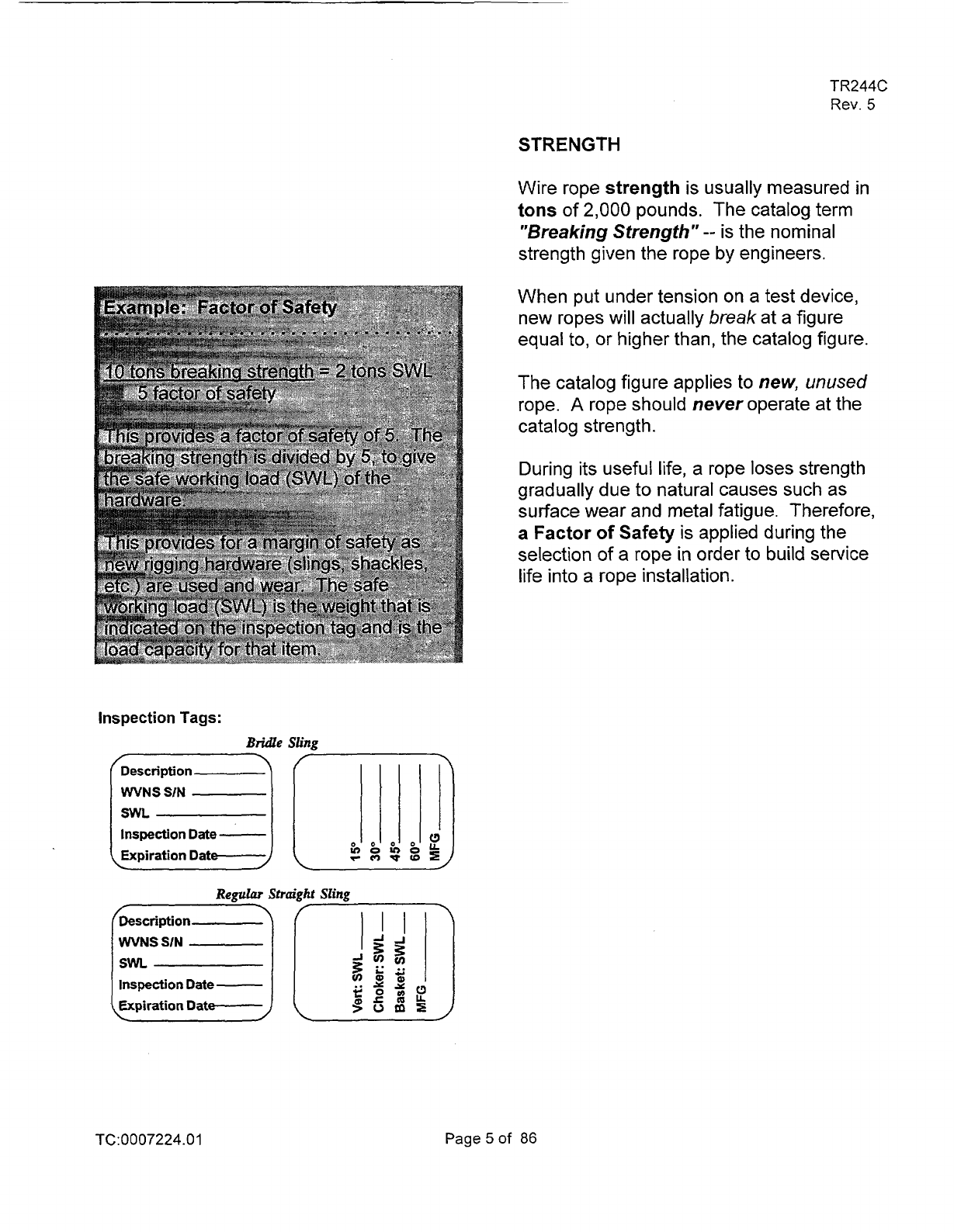
STRENGTH
Wire rope
strength is usually measured in
tons of
2,000
pounds. The catalog term
"Breaking Strength"
--
is the nominal
strength given the rope by engineers.
When put under tension on a test device,
new ropes will actually
break
at a figure
equal
to,
or higher than, the catalog figure.
The catalog figure applies
to
new,
unused
rope.
A
rope should never operate at the
catalog strength
.
During its useful life, a rope loses strength
gradually due to natural causes such as
surface wear and metal fatigue. Therefore,
a
Factor of
Safety
is
applied during the
selection
of
a
rope
in
order
to
build
service
life into a rope installation.
inspection
Tags:
Bridle
Sling
Description
Inspection
Date
-
Expiration Dat
rcrlwtBI
Regular
Straight
Sling
Description
WVNS
SIN
leg
II
SWL
TC:0007224.01
Page5of
86
the
Did
Ratio
is
expresse
TR244C
Rev.
5
Sling Eye Design
Sling eyes are designed to provide what
amount to "small inverted slings" at the ends
of the sling body. Therefore, the width of
the eye opening will be affected by the
same general forces which apply to legs
of a
sling rigged as a basket.
A sling eye should never be used over a
hook or pin with a body diameter larger that
the natural width
of
the eye. Never force an
eye onto a hook.
On the other hand, the eye should always
be used on a hook
or
pin with at least the
nominal diameter of the rope-since applying
the D/d Ratio shows an efficiency loss of
approximately
50% when the relationship is
less then
1/1
.
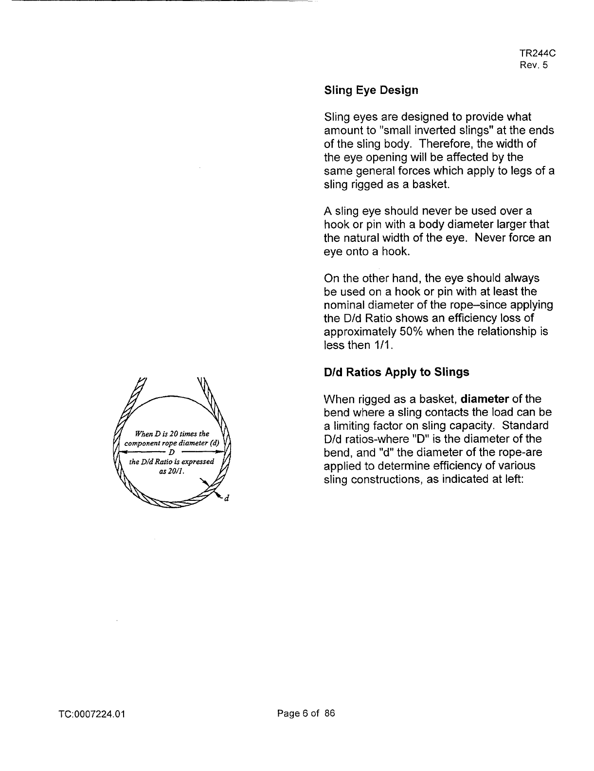
D/d Ratios Apply
to
Slings
When rigged as a basket, diameter of the
bend where a sling contacts the load can be
a limiting factor on sling capacity. Standard
D/d ratios-where
"D"
is the diameter of the
bend, and "d" the diameter of the rope-are
applied to determine efficiency of various
sling constructions, as indicated at left:
TC:
0007224.0
1
Page
6
of
86

TR244C
Rev.
5
Choker Hitch Rated Capacity Adjustment
For wire rope slings in choker hitch when
angle of choke is less than 135 degrees.
When a choker hitch is drawn tight at an
angle of less than
120
degrees, the Choker
Hitch Rated Capacity shown in the sling
Rated Capacity Tables must be reduced to
allow for
loss
of Rated Capacity.
In
controlled tests, where the angle was less
than
120
degrees, the sling body always
failed a the point
of choke when pulled to
destruction. Allowance for this phenomenon
must be made anytime a choker hitch is
used to shift, turn or control a load, or when
the pull
is
against the choke
in
a multi-leg
lift.
TC:0007224.01
Page7of 86

6
Inspection
Broken
WlreS
Severe wear
due
to
abrasion or
scraping
Birdcaging
Broken
or
damage
to
end
attachments
TR244C
Rev.
5
FREQUENT (PRE-USE) INSPECTION
Slings shall be visually inspected by the
person using the sling each day of their use.
This visual observation should be concerned
with discovering damage that may be an
immediate hazard.
Be sure to be aware of wire ropes in acid
type environments. Such an environment
can have a rapid corrosive affect on the wire
rope.
Kinks
Kinking
is
caused by
loops
that have been
drawntoo tightly as a result of improper
handling. Kinks are permanent distortions
and will require the rope or the damaged
section to be removed from service.
The following should be looked for in a
pre-use inspection:
1)
Broken wires.
2)
Severe localized abrasion or scraping.
3)
Kinking, crushing, birdcaging, or any
other damage resulting in distortion
of
the rope structure.
4)
Evidence of heat damage.
5)
End attachments that are cracked,
deformed, or worn to the extent that the
strength of the sling is substantially
affected
.
6)
Severe corrosion.
Review in Section
77.0
of
the
DOE
H&R
Manual. Subsection
I
I.
3.2
Wire Rope
Slings.
TC:0007224.01
Page8of
86
TR244C
Rev.
5
REVIEW QUESTIONS
WIRE ROPE
1.
The core
of
wire rope is the center
and serves to provide support and
maintain the position
of outer
strands.
A.
True
B.
False
2.
Of the three types
of
wire rope cores,
which is used most on site.
A.
Fiber
B.
Independent wire rope (IWRC)
C. Super fiber
D.
Strand
3.
The classification
6x19
used in wire
rope means:
A.
6
fibers and 19 wires
B.
6
strands of 19 wires
C.
6
inches
of
19 wires
D.
6 inches by
I9
inch wire
4.
A
right lay, are strands laid in a
direction.
A.
Left
B.
Counter clockwise
C. Right
D.
Band C
TC:0007224.01
Page9of
86
TR244C
Rev.
5
JNGS
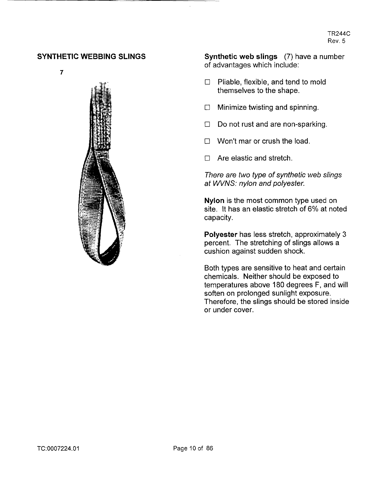
Synthetic web slings
(7)
have a number
of advantages which include:
0
Pliable, flexible, and tend to mold
themselves to the shape.
0
Minimize twisting and spinning.
0
Do
not rust and are non-sparking.
0
Won't mar
or
crush the load.
0
Are elastic and stretch.
There
are
two type
of
synthetic web slings
at
WVNS:
nylon
and
polyester.
Nylon is the most common type used on
site. It has an elastic stretch
of
6%
at noted
capacity.
Polyester has less stretch, approximately
3
percent. The stretching
of
slings allows a
cushion against sudden shock.
Both types are sensitive to heat and certain
chemicals. Neither should be exposed to
temperatures above
180
degrees
F,
and
will
soften on prolonged sunlight exposure.
Therefore, the slings should be stored inside
or under cover.
TC:0007224.01
Page
10
of
86
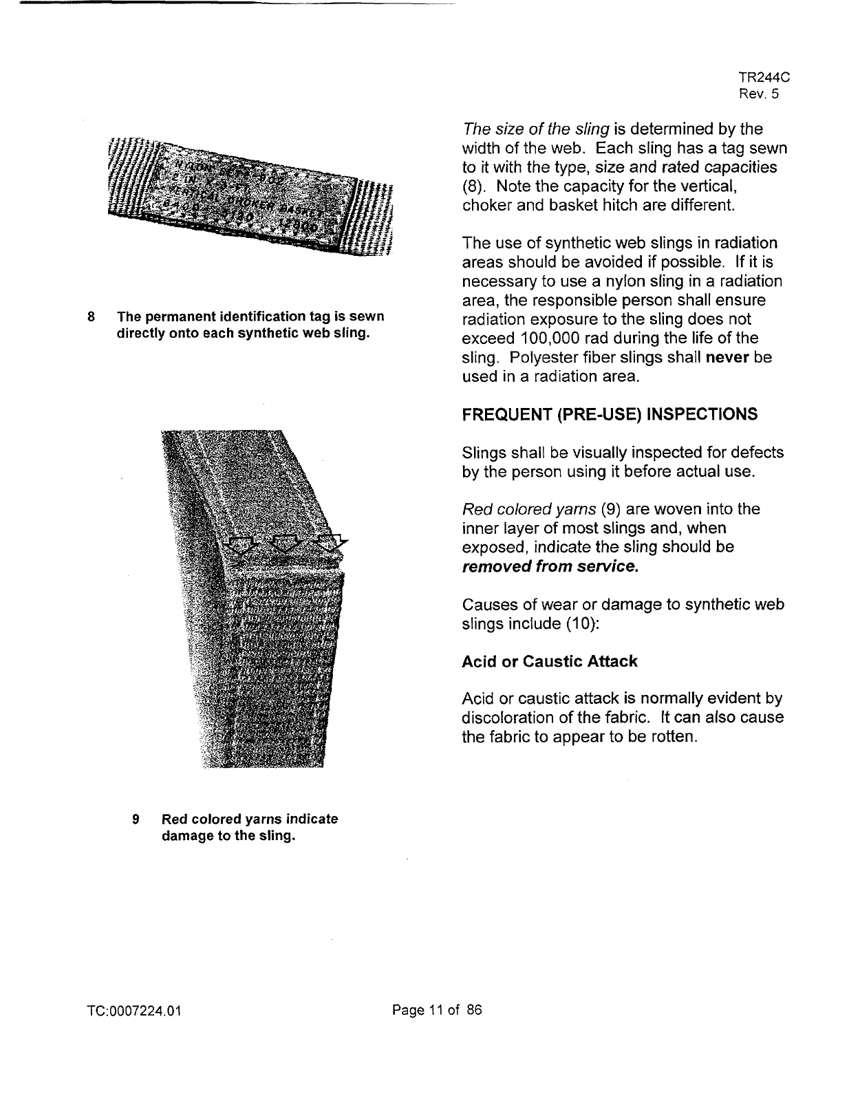
8
The permanent identification tag is sewn
directly onto each synthetic web sling.
9
Red colored yarns indicate
damage to the sling.
TR244C
Rev.
5
The
size
of
the
sling is determined by the
width of the web. Each sling has a tag sewn
to it with the type, size and rated capacities
(8). Note the capacity for the vertical,
choker and basket hitch are different.
The use of synthetic web slings in radiation
areas should be avoided if possible.
If it is
necessary to use a nylon sling in a radiation
area, the responsible person shall ensure
radiation exposure to the sling does not
exceed
100,000 rad during the life
of
the
sling. Polyester fiber slings shall
never
be
used in a radiation area.
FREQUENT
(PRE-USE)
INSPECTIONS
Slings shall be visually inspected for defects
by the person using
it
before actual use.
Red colored
yarns
(9)
are woven into the
inner layer of most slings and, when
exposed, indicate the sling should be
removed from service.
Causes
of
wear or damage to synthetic web
slings include
(I
0):
Acid
or
Caustic Attack
Acid or caustic attack
is
normally evident
by
discoloration of the fabric.
It
can
also cause
the fabric to appear to be rotten.
TC:
0007224.0
1
Page
11
of
86
TR244C
Rev.
5
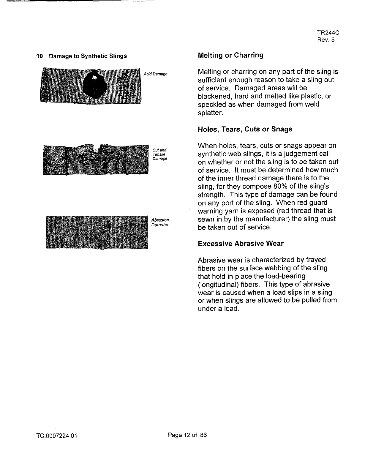
10
Damage to Synthetic Slings
Acid Damage
Cut
and
Tensile
Damage
Abrasion
Damabe
Melting or Charring
Melting or charring on any part of the sling is
sufficient enough reason to take a sling out
of
service. Damaged areas will be
blackened, hard and melted like plastic, or
speckled as when damaged from weld
s
p
I
atte r.
Holes,
Tears,
Cuts
or Snags
When holes, tears, cuts or snags appear on
synthetic web slings,
it
is a judgement call
on whether or not the sling
is
to be taken out
of service.
It
must be determined how much
of the inner thread damage there
is
to the
sling, for they compose
80%
of the sling's
strength. This type
of
damage can be found
on any port
of the sling. When red guard
warning yarn is exposed (red thread that is
sewn in by the manufacturer) the sling must
be taken out
of
service.
Excessive Abrasive Wear
Abrasive wear is characterized by frayed
fibers on the surface webbing
of
the sling
that hold in place the load-bearing
(longitudinal) fibers. This type of abrasive
wear is caused when a load slips in a sling
or when slings are allowed to be pulled from
under a load.
TC:
0007224.0
1
Page
12
of
86
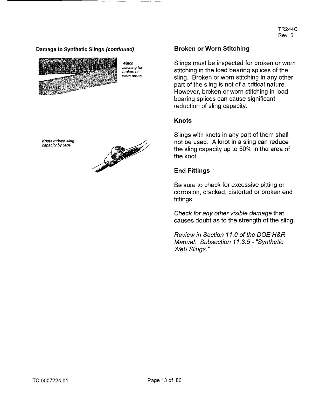
Damage to Synthetic Slings
(continued)
Watch
stitching
for
broken
or
worn
areas.
Knots
reduce
sling
capacify
by
50%.
TR244C
Rev.
5
Broken or Worn Stitching
Slings must be inspected for broken
or worn
stitching in the load bearing splices of the
sling. Broken or worn stitching in any other
part
of
the sling is not of a critical nature.
However, broken
or
worn stitching in load
bearing splices can cause significant
reduction of sling capacity.
Knots
Slings with knots in any part of them shall
not be used.
A
knot in a sling can reduce
the sling capacity up to
50% in the area
of
the knot.
End Fittings
Be
sure to check for excessive pitting or
corrosion, cracked, distorted or broken end
fittings.
Check for any other visible damage
that
causes doubt as to the strength of the sling.
Review in Section
11.0
of the
DOE
H&R
Manual. Subsection 1
1.3.5
-
"Synthetic
Web
Slings.
"
TC:0007224.01
Page
13
of
86
TR244C
Rev.
5
REVIEW QUESTIONS SYNTHETIC
WEB
SLINGS
1.
Most common synthetic web slings
are made of which of the following:
A. Polyester
B.
Nylon
C.
Acetone
2.
Which of the following
are
advantages of synthetic web slings
on wire rope.
A. Won't mar
or
crush the load
B.
Flexible
C.
Lighter and easier to handle
D.
All
of
the above
3.
When the red yarn shows through
a
worn area on the sling
it
is still
useable.
A. True
B.
False
4.
Synthetic web slings cannot be cut
if
used around sharp-cornered objects
without
a
protective cover.
A.
True
B.
False
TC:0007224.01
Page
14
of
86
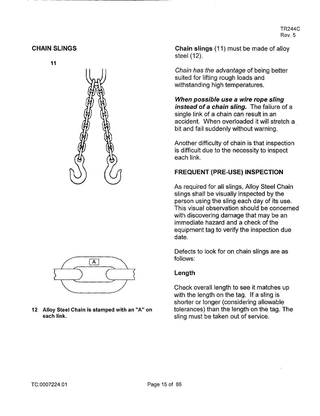
CHAIN
SLINGS
11
(Al
czI3
u
12
Alloy
Steel Chain is stamped with an
"A"
on
each link.
TR244C
Rev.
5
Chain slings
(I
1)
must be made of alloy
steel
(12).
Chain
has
the advantage
of
being better
suited for lifting rough loads and
withstanding high temperatures.
When possible
use
a
wire rope sling
instead
of
a
chain
sling.
The failure of a
single link of
a
chain can result in an
accident. When overloaded
it
will stretch
a
bit and fail suddenly without warning.
Another difficulty of chain is that inspection
is difficult due to the necessity to inspect
each link.
FREQUENT (PRE-USE) INSPECTION
As
required for all slings, Alloy Steel Chain
slings shall be visually inspected by the
person using the sling each day of its use.
This visual observation should be concerned
with discovering damage that may be an
immediate hazard and a check of the
equipment tag
to
verify the inspection due
date.
Defects to look for on chain slings are as
follows:
Length
Check overall length to see
it
matches up
with the length on the tag. If a sling is
shorter or longer (considering allowable
tolerances) than the length on the tag. The
sling must be taken out of service.
TC:
0007224.0
1
Page
15
of
86
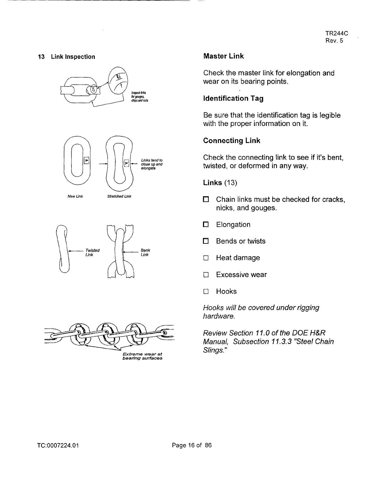
13
Link
Inspection
n
Links
tend
to
close
up
and
elongate
New
Link
stretched
Link
+---
Twisted
Benk
Link Link
Extreme wear at
bearing
surfaces
TR244C
Rev.
5
Master Link
Check the master link for elongation and
wear on its bearing points.
Identification Tag
Be sure that the identification tag is legible
with the proper information on
it.
Connecting
Link
Check the connecting link to see if it's bent,
twisted, or deformed in any way.
Links
(13)
Chain links must be checked for cracks,
nicks, and gouges.
Elongation
Bends or twists
0
Heatdamage
0
Excessive wear
0
Hooks
Hooks
will be covered under rigging
hardware.
Review Section
11.0
of
the
DOE
H&R
Manual, Subsection
11.3.3
"Steel Chain
Slings."
TC: 0007224
.O
1
Page
16
of
86
TR244C
Rev.
5
REVIEW
QUESTIONS
CHAIN
SLINGS
1.
Prior to use, the chain sling shall be
visually inspected by conducting a
li
n k-by4 n k inspection.
A. True
B.
False
2.
Shortening chain slings by bolting or
inserting the tip
of
the hook into
a
link is permitted.
A. True
B.
False
3.
To
avoid brittle fractures, in
temperatures less than
O'F,
sudden
loading of chain slings should be
avoided.
A.
True
B.
False
TC:0007224.01
Page
17
of
86
~__
METAL MESH SLINGS
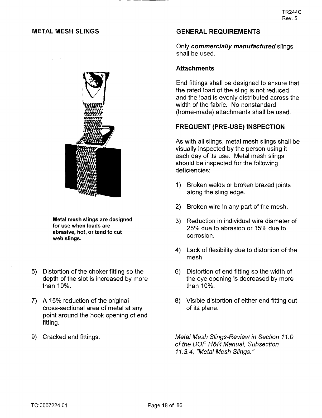
Metal mesh slings are designed
for use when loads are
abrasive,
hot,
or
tend
to
cut
web
slings.
5)
Distortion of the choker fitting
so
the
depth of the slot is increased by more
than
10%.
7)
A
15%
reduction of the original
cross-sectional area of metal at any
point around the hook opening of end
fitting.
9)
Cracked end fittings.
TR244C
Rev.
5
GENERAL REQUIREMENTS
Only
commercially manufactured slings
shall be used.
Attachments
End fittings shall be designed to ensure that
the rated load of the sling is not reduced
and the load is evenly distributed across the
width of the fabric. No nonstandard
(home-made) attachments shall be used.
FREQUENT (PRE-USE) INSPECTION
As
with all slings, metal mesh slings shall be
visually inspected by the person using
it
each day of its use. Metal mesh slings
should be inspected for the following
deficiencies:
I)
Broken welds or broken brazed joints
along the sling edge.
2)
Broken wire in any part of the mesh.
3)
Reduction in individual wire diameter of
25%
due to abrasion or
15%
due to
corrosion.
4)
Lack of flexibility due to distortion of the
mesh.
6) Distortion of end fitting
so
the width
of
the eye opening is decreased by more
than
10%.
8)
Visible distortion of either end fitting out
of its plane.
Metal Mesh Slings-Review in Section
7
1.0
of the
DOE
H&R
Manual, Subsection
1
7.3.4,
"Metal Mesh Slings.
"
TC:0007224.01
Page
18
of
86
TR244C
Rev.
5
GENERAL OPERATING PRACTICES
OF
SLINGS
a.
b.
C.
d.
e.
f.
g.
h.
The weight of the load shall be within
the rated capacity of the sling.
Slings shall not be shortened or
lengthened by knotting, twisting, with
wire rope clips or other methods not
approved by the sling manufacturer.
Slings that appear damaged shall not be
used.
Sharp corners in contact with the sling
should be padded to prevent damage to
the sling.
Shock loading should be avoided.
Sudden starts and stops increase (out
of
all proportion to the load), stress in
the sling and crane hoist rope.
Slings should be stored in an area
where they will not be subjected to
mechanical damage, corrosive action,
moisture, extreme heat, or kinking.
In a choker hitch, wire rope slings shall
be long enough
so
that the choker fitting
will choke on the rope body and never
on the fitting.
Sling angles less than
45
degrees
should be avoided.
TC:
0007224.0
1
Page
19
of
86
SPREADER BEAMS
15
TR244C
Rev.
5
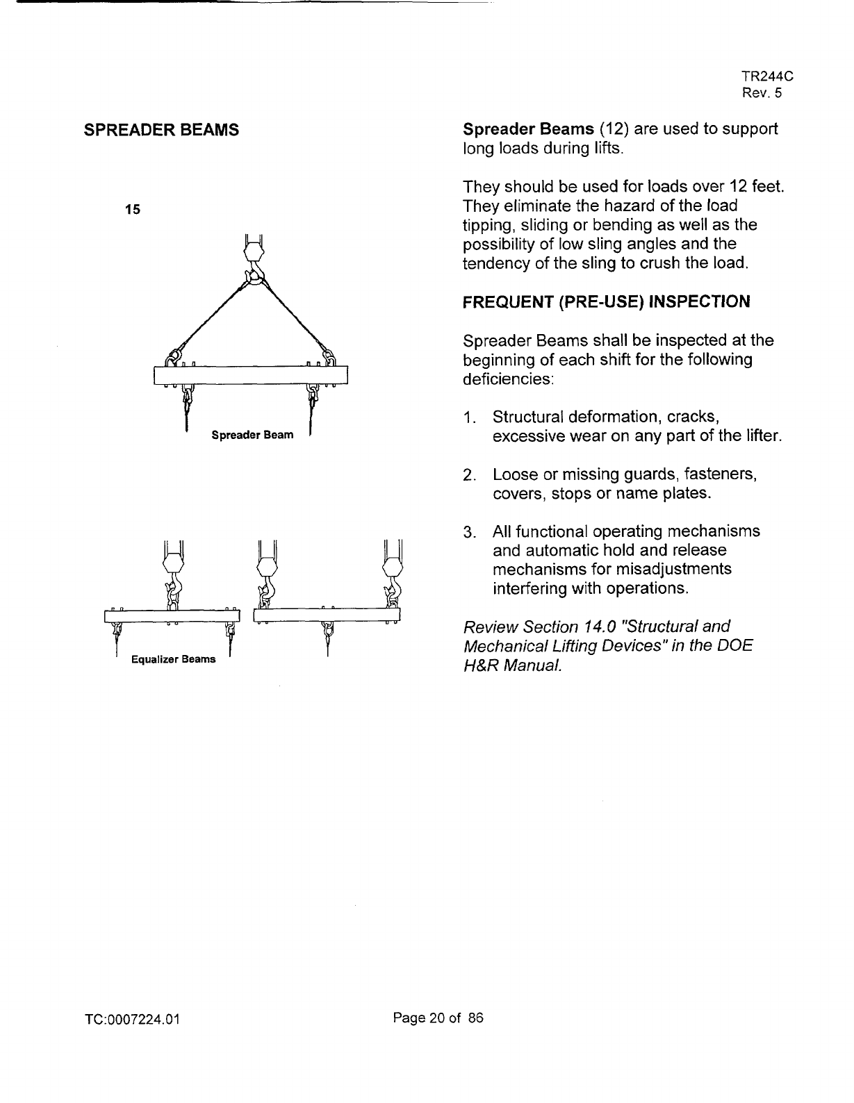
Spreader
Beams
(12)
are used to support
long loads during lifts.
They should be used for loads over
I2
feet.
They eliminate the hazard of the load
tipping, sliding or bending as well as the
possibility of low sling angles and the
tendency of the sling to crush the load.
F
REQU
E
N
T
(
P
RE-U
S
E)
I
NS
PE
CTlO
N
Spreader Beams shall be inspected at the
beginning of each shift for the following
deficiencies:
I.
Structural deformation, cracks,
excessive wear on any part of the lifter.
2.
Loose or missing guards, fasteners,
covers, stops or name plates.
3.
All
functional operating mechanisms
and automatic hold and release
mechanisms for misadjustments
i
n
t e rfer
i
n g with operations .
Review Section
14.0
"Structural and
Mechanical Lifting Devices" in the DOE
H&R
Manual.
TC:0007224.0
1
Page20of
86
TR244C
Rev.
5
REVIEW QUESTIONS
SPREADER BEAMS
I.
The operatorhigger when using a
spreader beam, can have it loaded
unequally, as a standard practice.
A.
True
B.
False
2.
Side pulls using a spreader beam
is
an acceptable practice.
A.
True
B.
False
3.
Prior to use the operator should
visually inspect the lifting device.
A.
True
B.
False
TC:0007224.01
Page21
of
86
TR244C
Rev.
5
RIGGING HARDWARE
16
Diameter
Anchor
Shackle
43
Chain
Shackle
17
Check
for
wear
Check
for
wear
and straightness
Check thaf pin
is seated
Check that schackle
is not "opening
up"
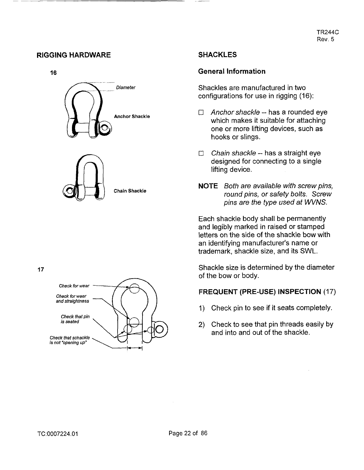
SHACKLES
General Information
Shackles are manufactured in
two
configurafions for use in rigging
(16):
0
Anchor shackle
-- has a rounded eye
which makes
it
suitable for attaching
one or more lifting devices, such as
hooks or slings.
0
Chain shackle
--
has a straight eye
designed for connecting to a single
lifting device.
NOTE
Both are available with screw pins,
round pins, or
safety
bolts.
Screw
pins are the type used at
WVNS.
Each shackle body shall be permanently
and legibly marked in raised or stamped
letters
on
the side of the shackle bow with
an identifying manufacturer's name or
trademark, shackle size, and
its
SWL.
Shackle size is determined by the diameter
of the bow or body.
FREQUENT
(PRE-USE) INSPECTION
(17)
1)
Check pin to see if it seats completely.
2)
Check to see that pin threads easily by
and into and out
of the shackle.
TC:0007224.01
Page22of
86
20
TR244C
Rev.
5
18
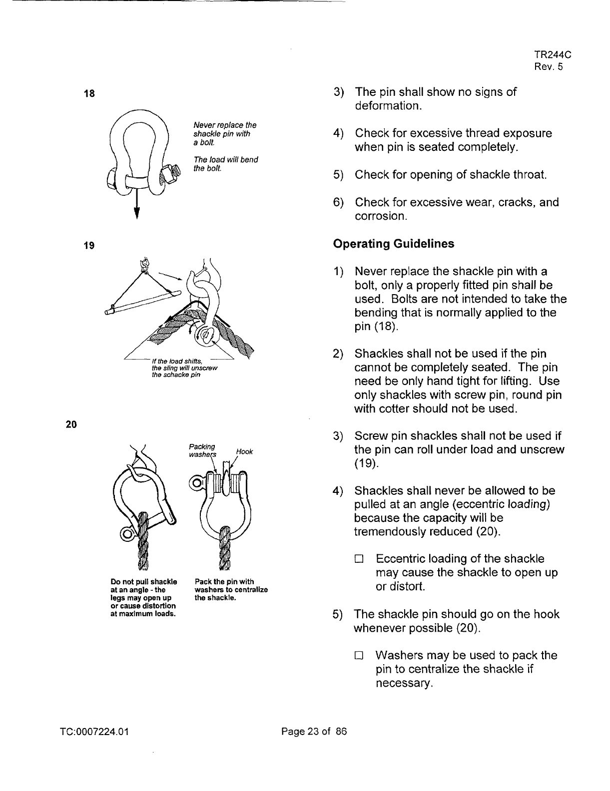
3)
The pin shall show no signs
of
deform at ion.
Never replace the
shackle
pin
with
4)
Check for excessive thread exposure
a
bolt.
when pin
is
seated completely.
The load wil/ bend
the
bolt.
5)
Check for opening
of
shackle throat.
6)
Check for excessive wear, cracks, and
v
corrosion.
19
Operating Guidelines
Never replace the shackle pin with a
bolt, only a properly fitted pin shall be
used. Bolts are not intended to take the
bending that is normally applied to the
pin
(18).
Shackles shall not be used if the pin
cannot be completely seated. The pin
the schkke
pin
need be only hand tight for lifting. Use
only shackles with screw pin, round pin
with cotter should not be used.
Screw pin shackles shall not be used if
the pin can roll under load and unscrew
(1
9).
Shackles shall never be allowed to be
pulled at an angle (eccentric
loading)
because the capacity
will
be
tremendously reduced
(20).
0
Eccentric loading
of
the shackle
may cause the shackle to open up
Do
not
pull
shackle
Pack the pin with
at an angle
-
the
washers to centralize
or
distort.
legs may open
up
the shackle.
or
cause distortion
at maximum loads.
The shackle pin should go on the hook
whenever possible
(20).
0
Washers may be used to pack the
pin
to centralize the shackle if
necessary.
TC:0007224.01 Page23of 86
21
TR244C
Rev.
5
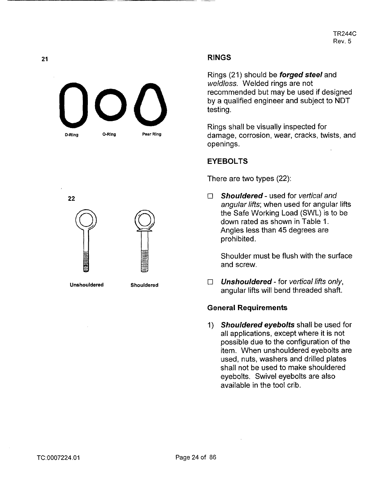
RINGS
Rings (21) should be forged steel and
000
D-Ring
0-Ring
Pear
Ring
22
Unshouldered Shouldered
weldless.
Welded rings are not
recommended but may be used if designed
by a qualified engineer and subject to NDT
testing.
Rings shall be visually inspected for
damage, corrosion, wear, cracks, twists, and
openings.
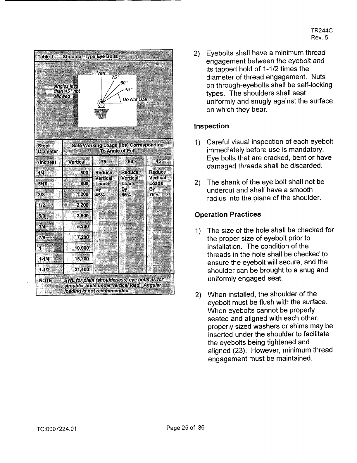
EYEBOLTS
There are two types (22):
0
Shouldered
-
used for
vertical and
angular lifts;
when used for angular lifts
the Safe Working Load (SWL) is to be
down rated as shown in Table
1.
Angles less than
45
degrees are
prohibited.
Shoulder must be flush with the surface
and screw.
0
Unshouldered
-
for
vertical lies
only,
angular lifts will bend threaded shaft.
General Requirements
1)
Shouldered eyebolts shall be used for
all applications, except where it is not
possible due to the configuration
of the
item. When unshouldered eyebolts are
used, nuts, washers and drilled plates
shall not be used to make shouldered
eyebolts. Swivel eyebolts are also
available in the tool crib.
TC:0007224.01
Page24of
86
TR244C
Rev.
5
2)
Eyebolts shall have a minimum thread
engagement between the eyebolt and
its tapped hold of
1-1 /2
times the
diameter of thread engagement. Nuts
on through-eyebolts shall be self-locking
types. The shoulders shall seat
uniformly and snugly against the surface
on which they bear.
Inspection
I)
Careful visual inspection of each eyebolt
immediately before use is mandatory.
Eye bolts that are cracked, bent or have
damaged threads shall be discarded.
2)
The shank
of
the eye bolt shall not be
undercut and shall have a smooth
radius into the plane of the shoulder.
Operation Practices
1)
The size of the hole
shall
be checked for
the proper size of eyebolt prior to
installation. The condition of the
threads in the hole shall be checked to
ensure the eyebolt will secure, and the
shoulder can be brought to a snug and
uniformly engaged seat.
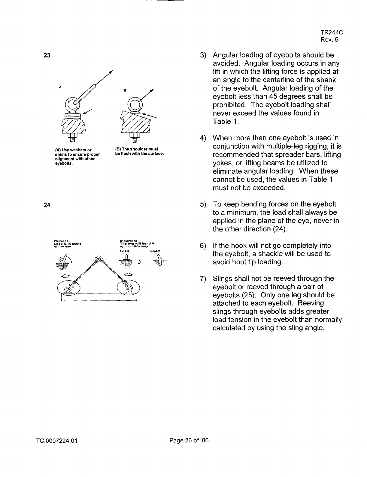
2)
When installed, the shoulder of the
eyebolt must be flush with the surface.
When eyebolts cannot be properly
seated and aligned with each other,
properly sized washers or shims may be
inserted under the shoulder to facilitate
the eyebolts being tightened and
aligned
(23).
However,
minimum
thread
engagement must be maintained.
TC:
0007224.0
1
Page25of
86
TR244C
Rev.
5
23
3)
Angular loading of eyebolts should be
avoided. Angular loading occurs in any
lift in which the lifting force is applied at
f
an angle to the centerline
of
the shank
of the eyebolt. Angular loading of the
eyebolt less than
45
degrees shall be
prohibited. The eyebolt loading shall
never exceed the values found in
Table
1.
4)
When more than one eyebolt
is
used in
conjunction with multiple-leg rigging, it is
(A)
Use
washers
or
(B)
The shoulder must
be
flush
with
the
surface.
shims to ensure proper
recommended that spreader bars, lifting
alignment with other
eyebolts.
yokes, or lifting beams be utilized to
eliminate angular loading. When these
cannot be used, the values in Table
1
must not be exceeded.
24
5)
To
keep bending forces on the eyebolt
to a minimum, the load shall always be
applied in the plane
of
the eye, never in
the other direction
(24).
connct
1"SDnDCt
Load
la
In
plane
me
eye
WIII
bend
if
of
the
eye
epplled
this
Wsy
6)
If the hook
will
not go completely into
Load
the eyebolt, a shackle will be used to
avoid hoot tip loading.
7)
Slings shall not be reeved through the
eyebolt or reeved through a pair of
eyebolts
(25).
Only one leg should be
attached to each eyebolt. Reeving
slings through eyebolts adds greater
load tension in the eyebolt than normally
calculated by using the sling angle.
TC:0007224.01
Page26of
86
25
TR244C
Rev.
5
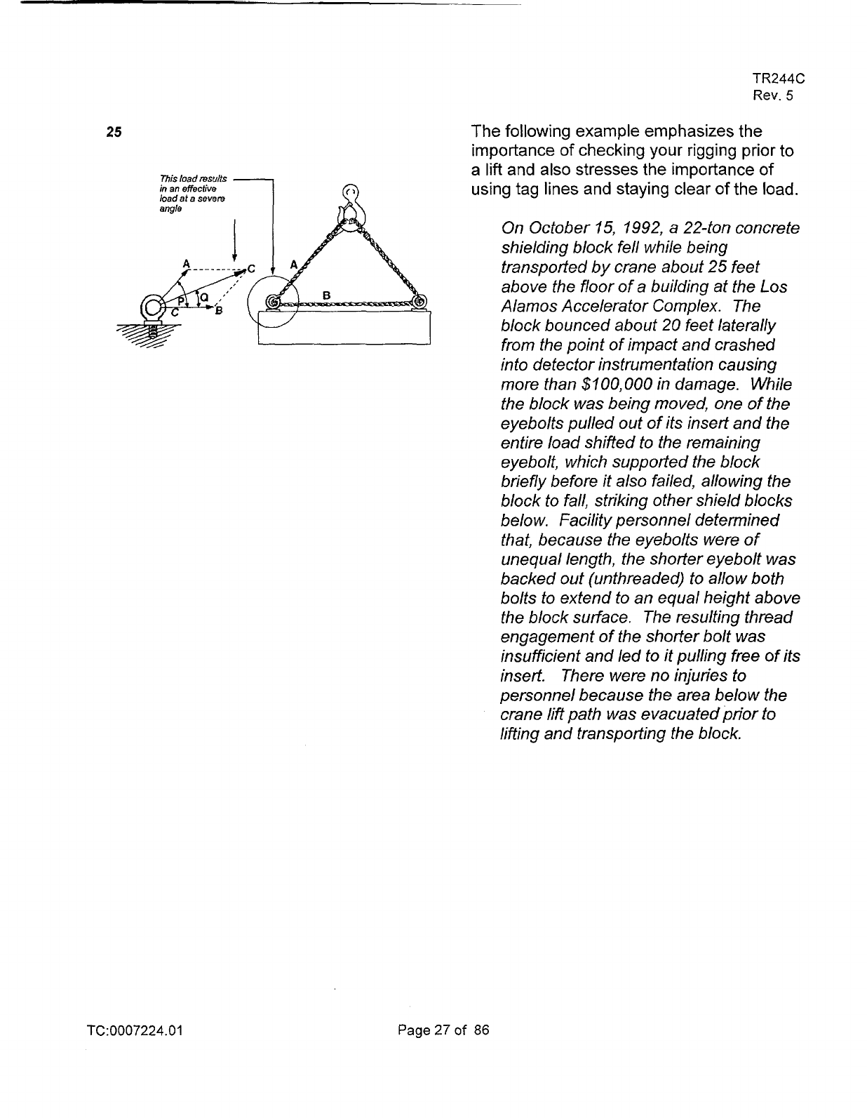
The following example emphasizes the
'7
importance
of
checking your rigging prior to
a
lift
and
also
stresses the importance
of
This toad
resuits
inanefictive
using tag lines and staying clear
of
the load.
load at a severe
angle
?-
E"-
4
On October 15, 1992, a 22-ton concrete
shielding block fell while being
transpotted by crane about 25 feet
above the floor
of
a building at the Los
Alamos Accelerator Complex. The
block bounced about
20
feet laterally
from the point of impact and crashed
into detector instrumentation causing
more than
$~OO,OUO
in damage. While
the block was being moved, one of the
eyebolts pulled out of its insert and the
entire load shifted to the remaining
eyebolt, which supported the block
briefly before it also failed, allowing the
block to fall, striking other shield blocks
below. facility personnel determined
that, because the eyebolts were
of
unequal length, the shorter eyebolt
was
backed out (unthreaded) to allow both
bolts to extend to an equal height above
the block surface. The resulting thread
engagement of the shorter bolt
was
insufficient and led to it pulling free of its
insert. There were no injuries to
personnel because the area below the
crane lift path was evacuated prior
to
lifting and transpotting the block.
TC:0007224.01
Page27of
86
26
TR244C
Rev.
5
HOOKS
Belanard
114
Load
Off
Center
lOO%
86%
of
load
Of
load
27
in
Off
Center
80%
ofloed
34
Off
Center
70%
of
load
Point
Loedlng
40%
oflosd
28
The safety latch helps
prevent
release
of
the
load.
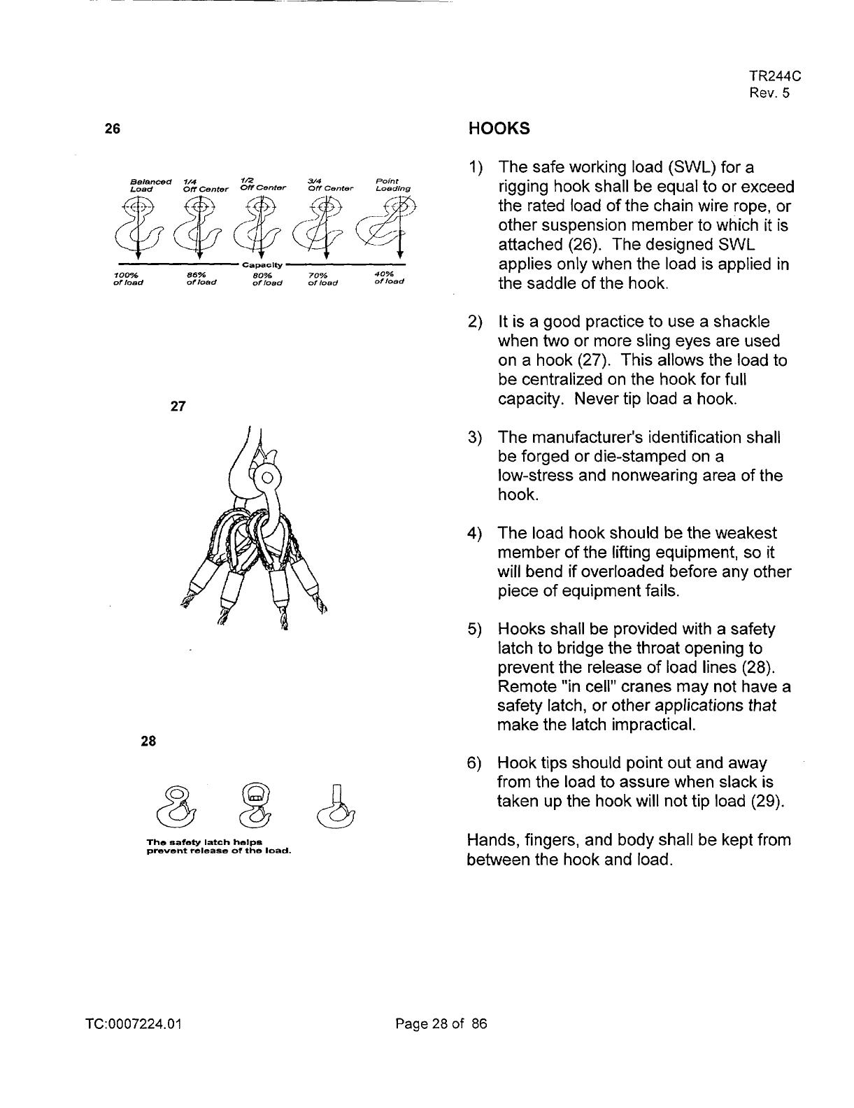
The safe working load
(SWL)
for a
rigging hook shall be equal to or exceed
the rated load of the chain wire rope, or
other suspension member to which it
is
attached (26). The designed
SWL
applies only when the load is applied in
the saddle of the hook.
It
is a good practice to use a shackle
when
two
or more sling eyes are used
on a hook
(27). This allows the load to
be centralized on the hook for full
capacity. Never tip load a hook.
The manufacturer's id en tification sha
I
I
be forged or die-stamped on a
low-stress and nonwearing area of the
hook.
The load hook should be the weakest
member of the lifting equipment, so
it
will bend
if
overloaded before any other
piece
of
equipment fails.
Hooks shall be provided with a safety
latch to bridge the throat opening to
prevent the release of load lines
(28).
Remote
"in
cell" cranes may not have a
safety latch, or other applications
that
make the latch impractical.
Hook tips should point out and away
from the load to assure when slack is
taken up the hook will not tip load (29).
Hands, fingers, and body shall be kept from
between the hook and load.
TC:0007224.01
Page28of
86
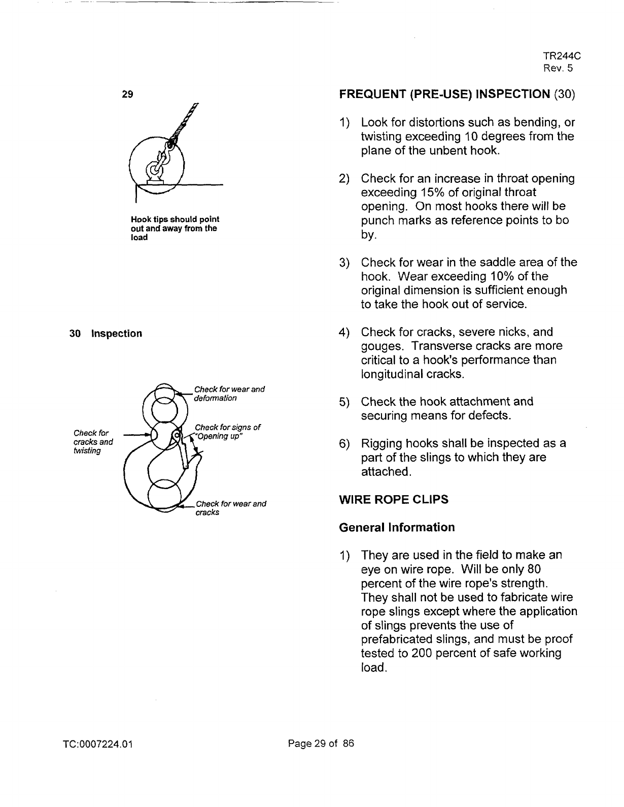
29
Hook
tips
should
point
out
and away
from
the
load
30
Inspection
Check
for
wear
and
Check
for
signs
of
Check
for
cracks
and
twisting
Check
for
wear
and
TR244C
Rev.
5
FREQUENT (PRE-USE) INSPECTION
(30)
Look for distortions such as bending, or
twisting exceeding
10
degrees from the
plane of the unbent hook.
Check for an increase
in
throat opening
exceeding
15% of original throat
opening. On most hooks there will be
punch marks as reference points to bo
by.
Check for wear in the saddle area of the
hook. Wear exceeding
10%
of the
original dimension is sufficient enough
to take the hook out of service.
Check for cracks, severe nicks, and
gouges. Transverse cracks are more
critical to a hook's performance than
longitudinal cracks.
Check the
hook
attachment and
securing means for defects.
Rigging hooks shall be inspected as a
part of the slings to which they are
attached.
WIRE ROPE CLIPS
General Information
I)
They are used in the field
to
make an
eye on wire rope. Will be only
80
percent of the wire rope's strength.
They shall not be used to fabricate wire
rope slings except where the application
of slings prevents the use
of
prefabricated slings, and must be proof
tested to
200
percent of safe working
load.
TC:
0007224.0
1
Page29of
86
TR244C
Rev.
5
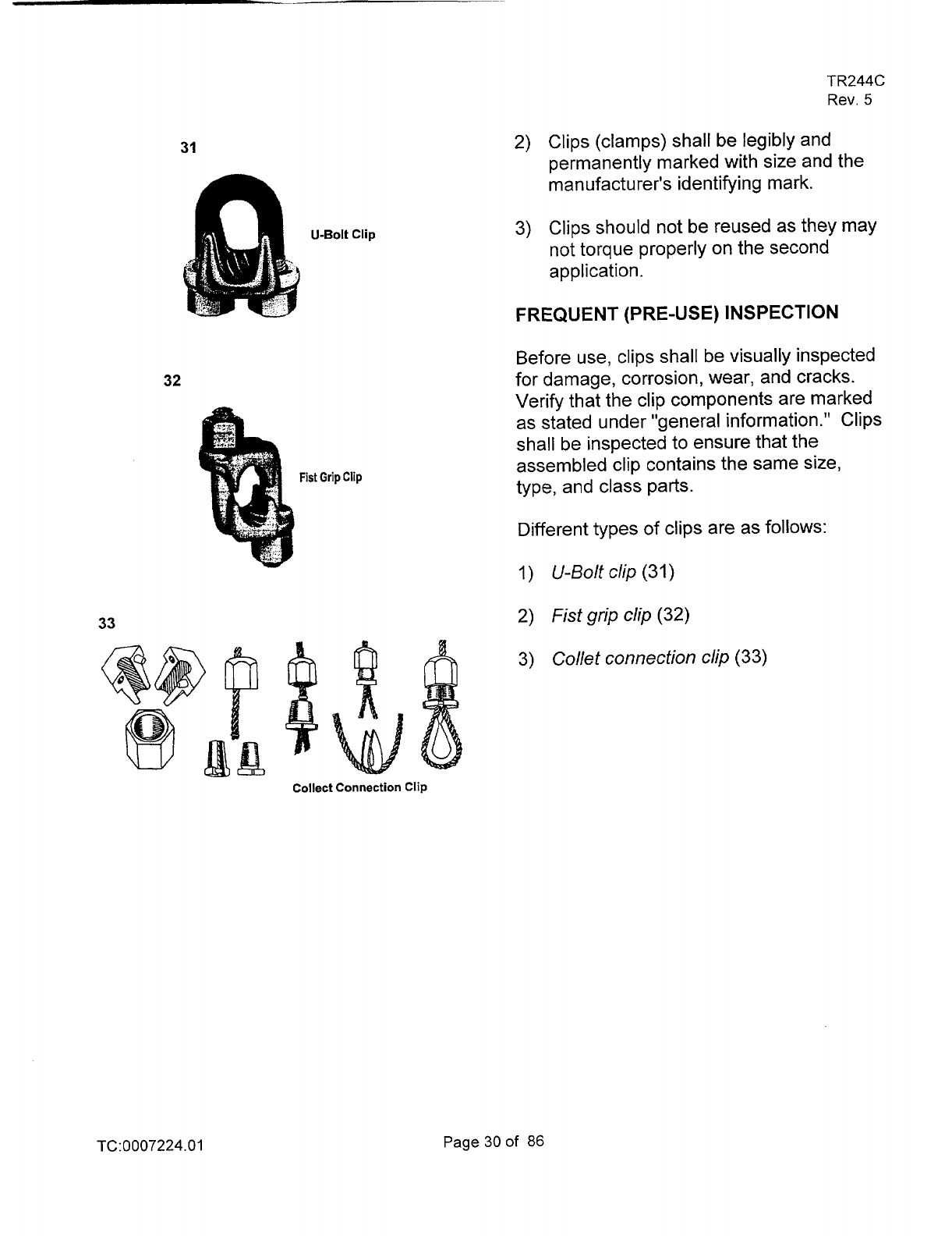
31
2)
Clips (clamps) shall be legibly and
permanently marked with size and the
manufacturer's identifying mark.
3) Clips should not be reused as they may
not torque properly
on
the second
application.
FREQUENT (PRE-US
E) IN SPECTl ON
Before use, clips shall be visually inspected
32
for damage, corrosion, wear, and cracks.
Verify that the clip components are marked
as stated under "general information." Clips
shall be inspected to ensure that the
assembled clip contains the same size,
type, and class parts.
Different types of clips are as follows:
1)
U-Bolt clip
(31)
33
2)
Fist grip clip
(32)
3)
Collet connection clip
(33)
Collect Connection Clip
TC:0007224.01
Page30of
86
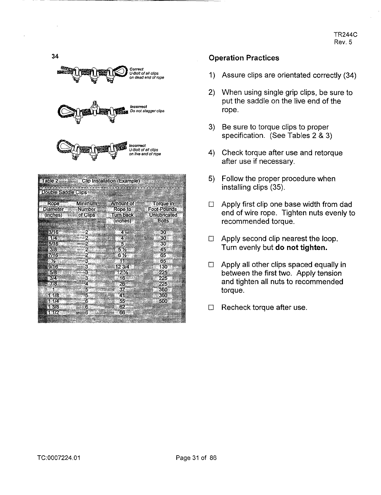
34
comt
U-Bolt
of
all clips
on
dead end
of
mpe
bcomt
Do
not stagger clips
lncomt
U-Bol
of
all clips
on
live
end
of
mpe
TR244C
Rev.
5
Operation Practices
Assure clips are orientated correctly
(34)
When using single grip clips, be sure to
put the saddle on the live end of the
rope.
Be sure to torque clips to proper
specification. (See Tables
2
&
3)
Check torque after use and retorque
after use if necessary.
Follow the proper procedure when
installing clips
(35).
Apply first clip one base width from dad
end of wire rope. Tighten nuts evenly to
recommended torque.
Apply second clip nearest the loop.
Turn evenly but do not tighten.
Apply all other
clips
spaced equally in
between the
first
two.
Apply tension
and tighten all nuts to recommended
torque.
Recheck torque after use.
TC:0007224.01
Page
31
of
86
TR244C
Rev.
5
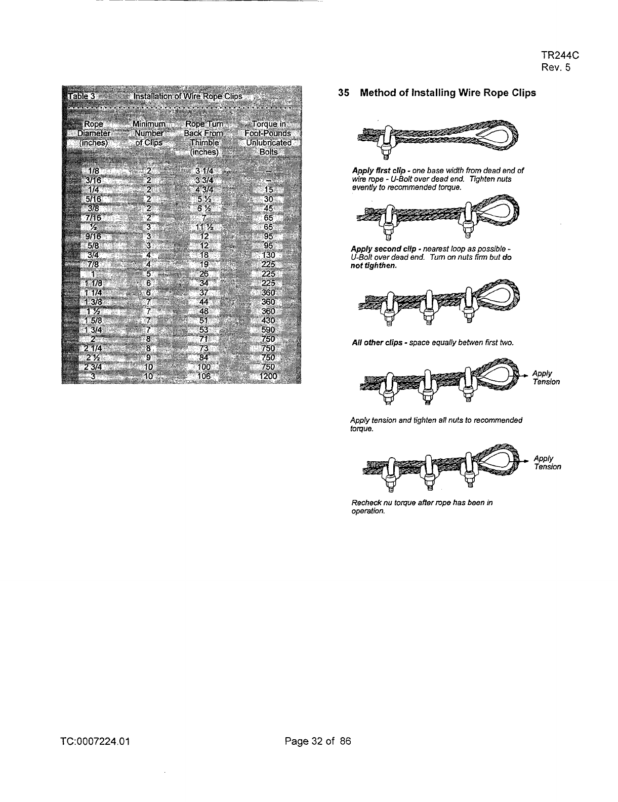
35
Method
of
Installing
Wire
Rope
Clips
Apply
first
clip
-
one base width
from
dead end
of
wire
rope
-
U-Bolt over dead end. Tighten nuts
evenUy to recommended torque.
Apply
second
clip
-
nearest
loop
as possible
-
U-Bolt over dead end.
Turn
on
nuts
firm
but
do
not
tighffien.
All
other
clips
-
space equally betwen first
two.
Apply
Tension
Apply tension and fighten
all
nuts
to
recommended
toque.
Apply
Tension
Recheck nu toque affer mpe has been
in
operation.
TC:
0007224
.O
1
Page32of
86

38
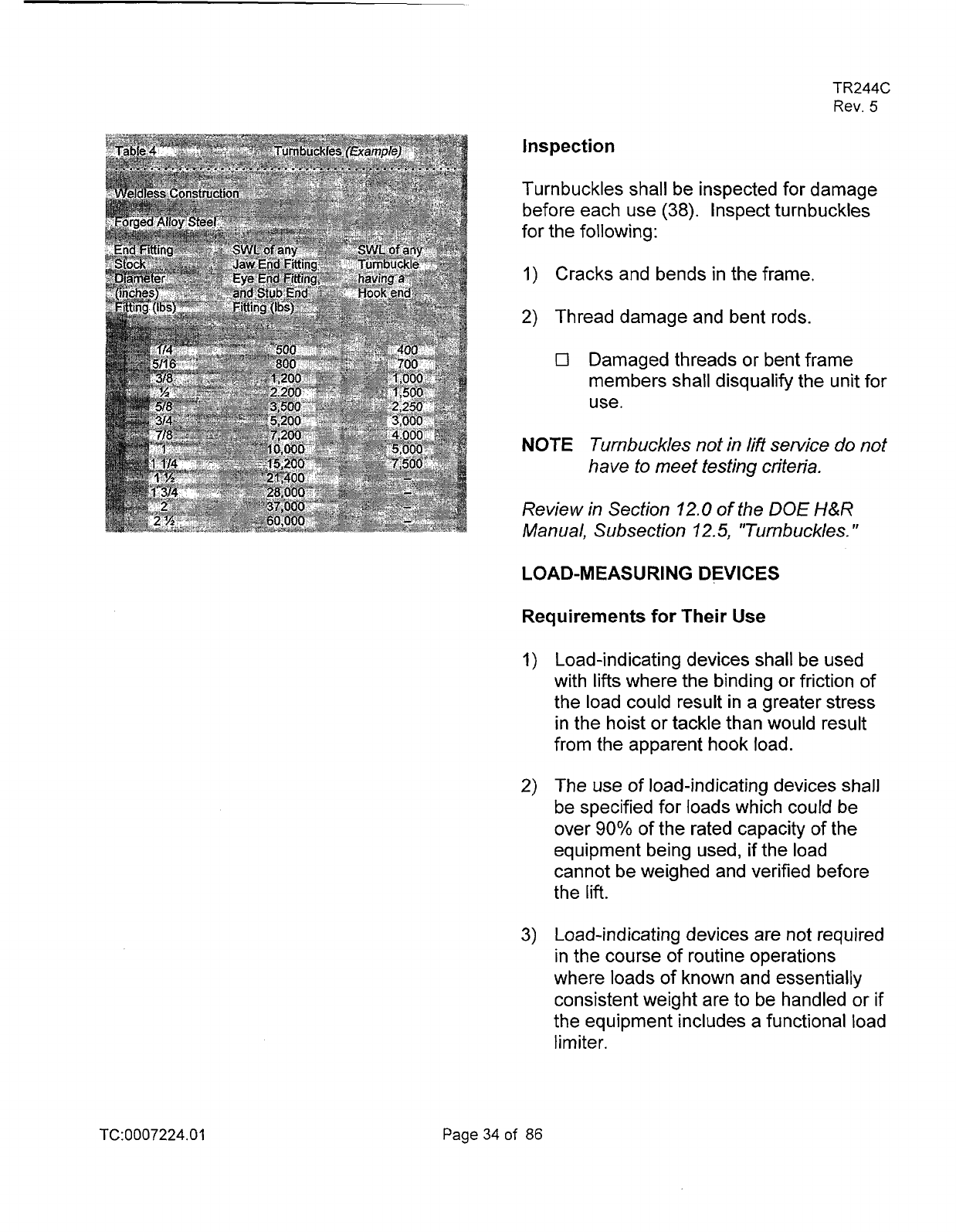
Turnbuckle End Fittings
n
Hook
€Ye
Jaw
Stub
(reduced
capacily)
37
Do
not
use
jam
nuts
Lock
wire
will hold
TR244C
Rev.
5
TURNBUCKLES
Genera
I
Inform
at
i
o
n
Turnbuckles should be avoided;
however if they are used in a rigging
system, that system must be designed,
analyzed, and approved by a qualified
engineer.
Turnbuckles used in hoisting and rigging
operations shall be fabricated from
forged alloy steel.
3)
If a turnbuckle is used in an application
where vibration
is
present, the end
fittings should be secured to the frame
with lock pins or wires to prevent them
from turning and loosening. Locknuts
(jam nuts) shall not be used. Locknuts
can significantly increase the stresses
imposed upon the threads
(37).
4)
Before placing turnbuckles in lifting
service, a permanent identification tag
shall be affixed.
Check
for
cracks
and bends
TC:0007224.01
Page33of 86
TR244C
Rev.
5
Inspection
Turnbuckles shall be inspected for damage
before each use
(38). Inspect turnbuckles
for the following:
1)
Cracks and bends in the frame.
2)
Thread damage and bent rods.
0
Damaged threads or bent frame
members shall disqualify the unit for
use.
NOTE
Turnbuckles
not
in
lift
service
do
not
have to meet testing criteria.
Review in Section
12.0
of
the
DOE
H&R
Manual, Subsection 12.5, "Turnbuckles.
I'
LOAD-M EASU
RI
NG DEVICES
Requirements for Their Use
Load-indicating devices shall be used
with
lifts
where the binding or friction of
the load could result in a greater stress
in the hoist or tackle than would result
from the apparent hook load.
The use of load-indicating devices shall
be specified for loads which could be
over
90%
of the rated capacity of the
equipment being used, if the load
cannot be weighed and verified before
the
lift.
Load-indicating devices are not required
in the course of routine operations
where loads of known and essentially
consistent weight are
to
be handled
or
if
the equipment includes a functional load
limiter.
TC: 0007224.0
1
Page
34
of
86
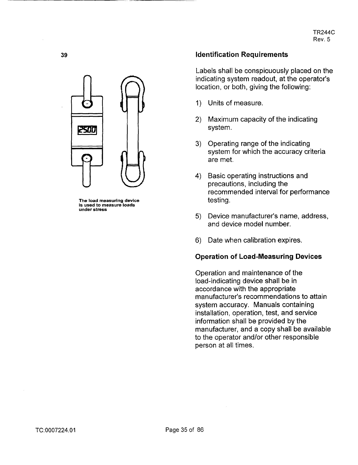
39
The load measuring device
is used
to
measure loads
under stress
TR244C
Rev.
5
identification Requirements
Labels shall be conspicuously placed on the
indicating system readout, at the operator's
location, or both, giving the following:
Units
of measure.
Maximum capacity of the indicating
system.
Operating range of the indicating
system for which the accuracy criteria
are met.
Basic operating instructions and
precautions, including the
recommended interval for performance
testing.
Device manufacturer's name, address,
and device model number.
Date when calibration expires.
Operation of Load-Measuring
Devices
Operation and maintenance
of
the
load-indicating device shall be in
accordance with the appropriate
manufacturer's recommendations
to
attain
system accuracy. Manuals containing
installation, operation, test, and service
information shall be provided by the
manufacturer, and a copy shall be available
to the operator and/or other responsible
person at all times.
TC:0007224.01
Page35of
86
TR244C
Rev.
5
Range
The Load-indicating system should be
selected to ensure the expected load is
between
10%
to
70%
of full scale indication.
Example:
You would not select a
dynamometer with
2000
Ibs. Capacity to
pick a
1700 Ib load. (1700 Ibs.
Is
85%
of the
dyno's capacity)
Operation
Checks
The load-indicating system shall include a
means for the operator or another
responsible person to determine that
it
is
operative before crane use. And the
readout device shall be located
so
the
operator, and/or other signal person, can
obtain readings from the normal working
position.
Review in Section
12.0
of
the
DOE
H&R
Manual,
Subsection,
1
2.8,
"Load-lndica
fing
De vices.
"
TC:0007224.0
1
Page36of
86
TR244C
Rev.
5
REVIEW QUESTIONS
RlGG
I
N
G
HARDWARE
1.
The size
of
the shackle
is
determined
by the diameter
of
the
A.
Body
B.
Bolt
C.
Pin
D.
Opening
2.
The shackle pin should
go
on
the
crane hook whenever possible.
A.
True
B.
False
3.
The shackle shall not be used
if
the
pin
cannot be completely seated with
hand pressure.
A.
True
B.
False
4.
Shouldered eyebolts can be used
with angles to
45
degrees
with
a
decrease
in
its
capacity.
A. True
B.
False
5.
Unshouldered eyebolts can be used
for vertical and angular
lifts.
A.
True
B.
False
6. Eyebolts should have a minimum
thread engagement between the
eyebolt and
its
tapped hole
of
1-112
times the diameter of the thread.
A.
True
8.
False
TC: 0007224.0
1
Page37of
86
7.
Eyebolts should be pulled or loaded
in
the plane of the eye.
A.
True
B.
False
8.
To prevent
tip
loading, when using a
sling with a hook attachment, the
hook tip should point out and away
from the load.
A. True
6.
False
9.
To
carry the rated load
of
a hook, the
load should
sit
in
the saddle
of
the
hook.
A.
True
B.
False
IO.
Its
a good practice to
use
a shackle
when
two
or more sling eyes are
used on a hook to center the load on
the hook.
A. True
B.
False
1
I.
Wire rope clips must have the U-bolt
section
on
the dead or short end of
the rope.
A.
True
B.
False
TR244C
Rev.
5
12. Wire rope clips will develop
approximately
80
percent
of
the rope
strength
.
A.
True
B.
False
13.
Wire rope clips can
be
reused
numerous times.
A.
True
B.
False
14.
When Turnbuckles are used, they are
designed as part of the rigging
system.
A.
True
B.
False
15.
Load indicating devices should be
used for which of the following:
A.
Routine operations
B.
Where binding or friction can occur
C.
Loads
which cannot be weighted
D.
Both
Band
C
TC:0007224.01
Page38of
86
TR244C
Rev.
5
INSPECTION
TAG
INSPECTION
TAG
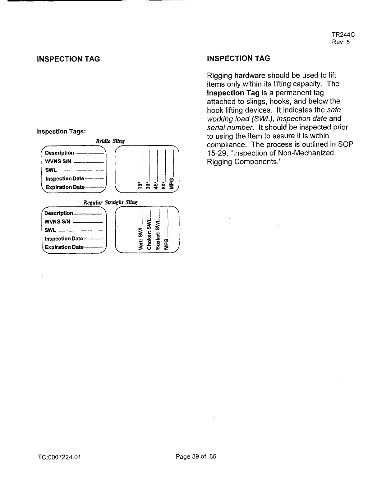
Rigging hardware should
be
used to lift
items only within its lifting capacity. The
Inspection
Tag
is a permanent tag
attached to slings, hooks, and below the
hook lifting devices.
It
indicates the
safe
working
load
(S
WL),
inspection date
and
serial number.
It should be inspected prior
to using the item to assure
it
is within
compliance. The process is outlined in
SOP
15-29,
"Inspection of Non-Mechanized
Rigging Components."
Inspection
Date
-
TC:
0007224
.O
1
Page39of
86
CRITICAL LIFTS
TR244C
Rev.
5
GENERAL
This section specifies the guidelines for
critical
lift
determination and delineates the
requirements applicable to planning and
performing a critical
lift
in a safe and
judicious manner as is outlined in Section
2
of the
DOE
H&R
manual.
Critical Lift Determination
An appointed person shall classify each lift
into one
of the DOE categories (ordinary
and critical) prior to planning the lift.
A
lift
shall be designated as
a
critical
lift
if
collision, upset, or dropping could result in
any one of the following:
a.
Damage that would result in
unacceptable delay to schedule or other
significant program impact, i.e.,
loss
of
vital data.
b.
Significant release of radioactive/other
hazardous material or other undesirable
cond it ions.
C.
Unacceptable risk of personnel injury or
significant adverse health impact
(on-site or off-site).
d.
Undetectable damage that would
jeopardize future operations or the
safety
of a facility.
NOTE
A
lift should also be designated as
critical if the load requires
exceptional care in handling
because
of
size, weight,
close-tolerance installation, high
susceptibility to damage, or other
unusual factors.
TC:0007224.0
1
Page
40
of
86

TR244C
Rev.
5
Critical
Lift
Requirements
The operating organization shall appoint a
person-in-charge (PIC)
of
the entire lifting
operation. This person shall meet the
definitions of appointed, designated, and
qualified, as set forth in Section
6.0
of the
DOE
Hoisting and Rigging Manual and shall
be present at the lift site during the entire
lifting operation.
The PIC shall ensure that a pre-job plan or
procedure is prepared which defines the
operation and shall include the following:
a. Identification
of
the item(s) to be moved,
the weight, dimensions, center of
gravity, and the presence of hazardous
or toxic materials.
b. Identification of operating equipment
[crane(s)], to be used by type and rated
capacity.
c.
Rigging sketches which shall include, as
applicable:
0
Identification and rated capacity
of
sling, lifting bars, rigging
accessories, and below-the-hook
lifting devices
0
Load-indicating devices
Load vectors
0
Lifting points
TC:0007224.01
Page41
of
86
TR244C
Rev.
5
Sling angels
Boom and swing angles
Method of attachment
Crane orientations
Other factors affecting equipment
capacity.
d. Operating procedures including special
instructions to operators including
rigging precautions and safety
measures to be followed as applicable.
Experienced operators who have been
trained and qualified to operate the specific
equipment to be used shall be assigned to
make the lift.
Only designated, qualified signalers shall
give signals to the operator. However, the
operator shall obey a
STOP
signal at all
times, no matter who gives the signal.
The procedure and rigging sketches shall be
reviewed and approved by the responsible
manager or designee and the responsible
oversight organization, i.e., Safety,
QNQC,
prior to making the lift.
A prelift meeting involving participating
personnel shall be conducted prior to
making a critical
lift.
The critical
lift
plan/procedure shall be reviewed and
questions shall be resolved.
TC:
0007224.0
1
Page
42
of
86
TR244C
Rev.
5
REVIEW
QUESTIONS
Critical Lifts
1.
List the four factors which would
classify a lift as critical.
2.
A
person-in-charge
(PIC)
is required
for a critical lift.
A. True
B.
False
3.
List three main items the
person-in-charge is required to
do for
critical lifts.
TC:0007224.0
1
Page
43
of
86
TR244C
Rev.
5
GENERAL HOISTING AND RIGGING
PRACTICES
Guidelines are outlined in SOP
00-38,
"Administration
of
Hoisting and Rigging
Activities." This procedure outlines the
procedural steps for the execution and
control of hoisting and rigging activities at
the
WVDP.
Review this document for the
requirements of work documents, pre-job
briefing, and inspection and load tests.
Operator
Rules
The operator shall be familiar with the
crane or hoist operating characteristics
and be aware
of
the safety rules for
ope rat0 rs.
For mobile cranes barricade accessible
areas within the swing radius
of
the rear
of the rotating superstructure of the
crane to prevent anyone from being
struck or crushed by the crane.
No
crane, hoist, or rigging hardware
shall be loaded beyond the rated
capacity, except for test purposes.
For critical lifts, the PIC
is
responsible
for verifying that the total load is
accurately determined before the lift and
will not exceed the equipment's rated
capacity.
TC:0007224.01
Page
44
of
86
5)
Hoisting and rigging for ordinary lifts that
require more than one person, i.e., an
operator and a rigger(s), shall have a
designated leader. The designated
leader
shall
be
present at the
lift
site for
the entire lift operation.
a)
Hoisting and rigging operations for
ordinary lifts require a designated
leader who shall be present at the
lift
site during the entire lifting
operation.
If
the lift is being made
by only one person, that person
assumes all responsibilities of the
designated leader.
b) Leadership designation may be by
written instructions, specific verbal
instructions for the particular job, or
clearly defined responsibilities within
the crew's organizational structure.
c) The designated leader's
responsibility shall include the
following:
1.
Ensure that personnel involved
understand how the
lift
is to be
made.
2.
Ensure that the weight
of
the
load is determined, that proper
equipment and accessories are
selected, and that rated capacity
is not exceeded.
3.
Survey the lift site for
haza rdous/u nsafe conditions.
TR244C
Rev.
5
4.
Ensure that equipment is
properly set up and positioned.
5.
Ensure that a signaler is
assigned, if required, and is
identified to the operator.
6.
Direct the lifting operation to
ensure that the job is done
safely and efficiently.
7.
Stop the job when any
potentially unsafe condition is
recognized.
8.
Direct operations is an accident
or injury occurs.
d) The operator, or a designated
person, shall ensure that the crane
is still within the inspection interval.
e) The operator, or a designated
person, shall visually examine the
crane.
See
Section
7.0 of
the
DOE
H&R
Manual.
TC:0007224.01
Page45of
86
TR244C
Rev.
5
Moving
the
Load
1)
The signal person directing the lift (or if
a signal person is not used, the
operator) shall ensure the following:
0
The load is well secured and
balanced in the sling or lifting device
before it is lifted more than a few
inches.
0
That the load path is clear of
obstruct ions.
2)
Before starting to lift, the operator will
ensure the following conditions are met:
0
Hoist rope or chain is not kinked.
0
Multiple-part lines are not twisted
around each other.
0
If the load line (rope or chain)
is
slack, ensure that the line seats on
the sheaves, sprockets, etc., as the
slack is removed.
See that the load line is plumb to
prevent side pull.
Two degrees out
of plumb is considered excessive.
It
introduces stresses in the crane that
were not necessarily accounted for
in the design of the crane or hoist.
It may result in bridge or trolley
brakes holding the load. Or can
possibly cause damage to the rope
as it runs up the side
of
the sheave
or drum. The load center
of
gravity
should have the hook above it.
TC: 0007224.0
1
Page
46
of
86
40
Keep
the
load
under
control
at
all
times
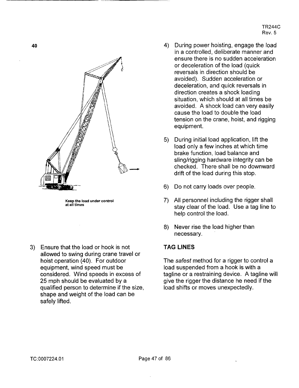
3)
Ensure that the load or hook is not
allowed to swing during crane travel or
hoist operation
(40).
For outdoor
equipment] wind speed must be
considered. Wind speeds in excess of
25
mph should be evaluated by a
qualified person to determine if the size,
shape and weight of the load can be
safely lifted.
TR244C
Rev.
5
During power hoisting, engage the load
in a controlled, deliberate manner and
ensure there is no sudden acceleration
or deceleration of the load (quick
reversals
in
direction should be
avoided). Sudden acceleration or
deceleration] and quick reversals
in
direction creates a shock loading
situation, which should at all times be
avoided.
A
shock load can very easily
cause the load to double the load
tension on the crane, hoist, and rigging
equipment.
During initial load application, lift the
load only a few inches at which time
brake function] load balance and
slinglrigging hardware integrity can be
checked. There shall be no downward
drift of the load during this stop.
Do
not carry loads over people.
All
personnel including the rigger shall
stay clear of the load. Use a tag line to
help control the load.
Never rise the load higher than
necessary.
TAG
LINES
The
safest
method for a rigger to control a
load suspended from a
hook is with a
tagline or a restraining device.
A
tagline will
give the rigger the distance he need if the
load shifts or moves unexpectedly.
TC:
0007224.0
1
Page
47
of
86
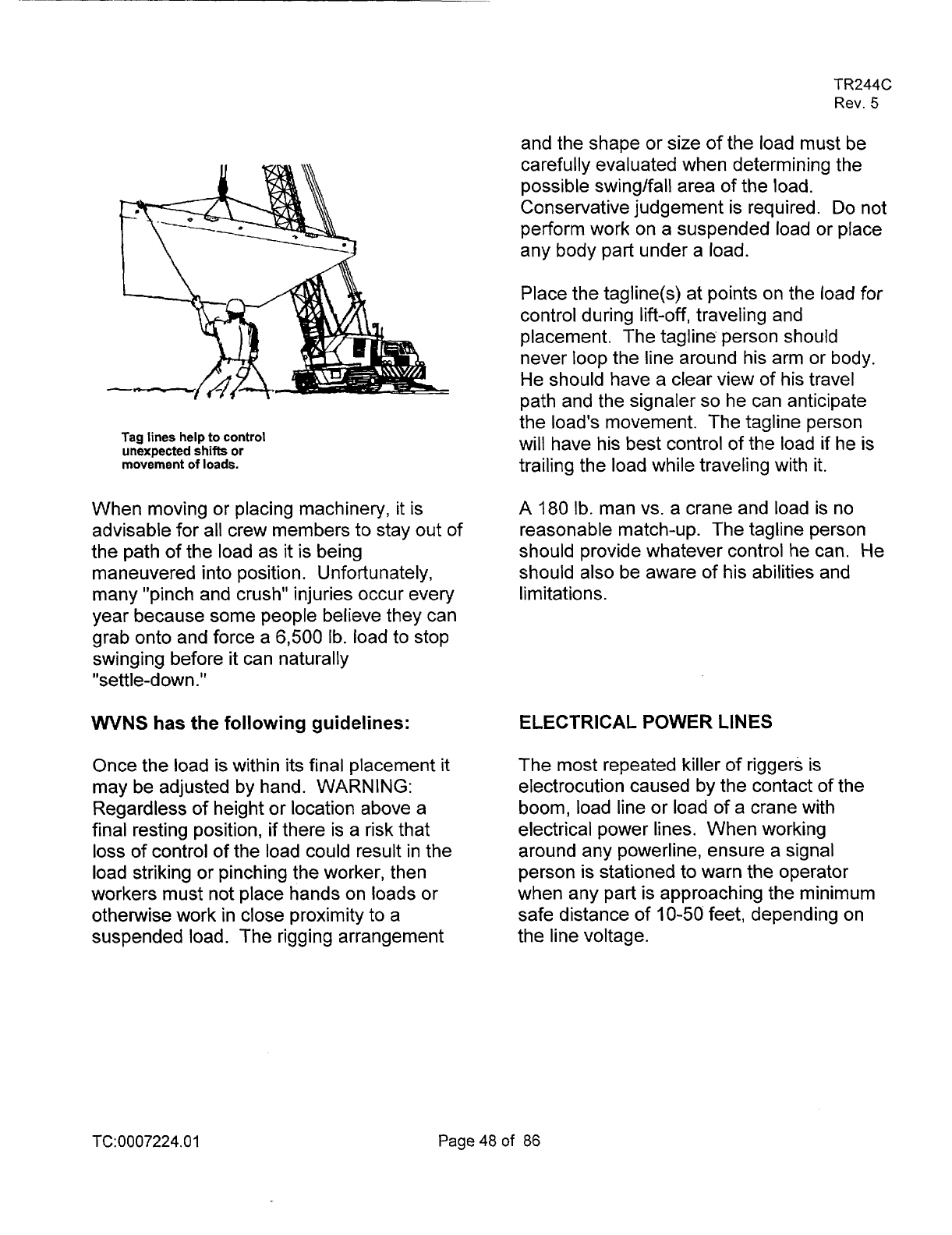
Tag lines
help
to control
unexpected
shifts
or
movement
of
loads.
When moving or placing machinery, it is
advisable for all crew members to stay out of
the path of the load as
it
is being
maneuvered into position. Unfortunately,
many "pinch and crush" injuries occur every
year because some people believe they can
grab onto and force a
6,500 Ib. load to stop
swinging before
it
can naturally
"settle-down."
WNS
has the following guidelines:
Once the load
is
within its final placement
it
may be adjusted by hand. WARNING:
Regardless
of
height or location above a
final resting position, if there is a risk that
loss
of control
of
the load could result in the
load striking or pinching the worker, then
workers must not place hands on loads or
otherwise work in close proximity to a
suspended load. The rigging arrangement
TR244C
Rev.
5
and the shape or size of the load must be
ca ref u
I
I
y eva Iuated when determining the
possible swing/fall area
of the load.
Conservative judgement is required.
Do
not
perform work on a suspended load or place
any body part under a load.
Place the tagline(s) at points on the load
for
control during lift-off, traveling and
placement. The tagline' person should
never loop the line around his arm or body.
He should have a clear view of his travel
path and the signaler
so
he can anticipate
the load's movement. The tagline person
will have his best control of the load if he is
trailing the load while traveling with it.
A
180
Ib. man vs. a crane and load is no
reasonable match-up. The tagline person
should provide whatever control he can. He
should also be aware of his abilities and
limitations.
ELECTRICAL
POWER LINES
The
most repeated killer of riggers is
electrocution caused by the contact
of
the
boom, load line or load
of
a crane with
electrical power lines. When working
around any powerline, ensure a signal
person is stationed to warn the operator
when any part is approaching the minimum
safe distance of
10-50
feet, depending on
the line voltage.
TC:0007224.0
1
Page48of 86
TR244C
Rev.
5
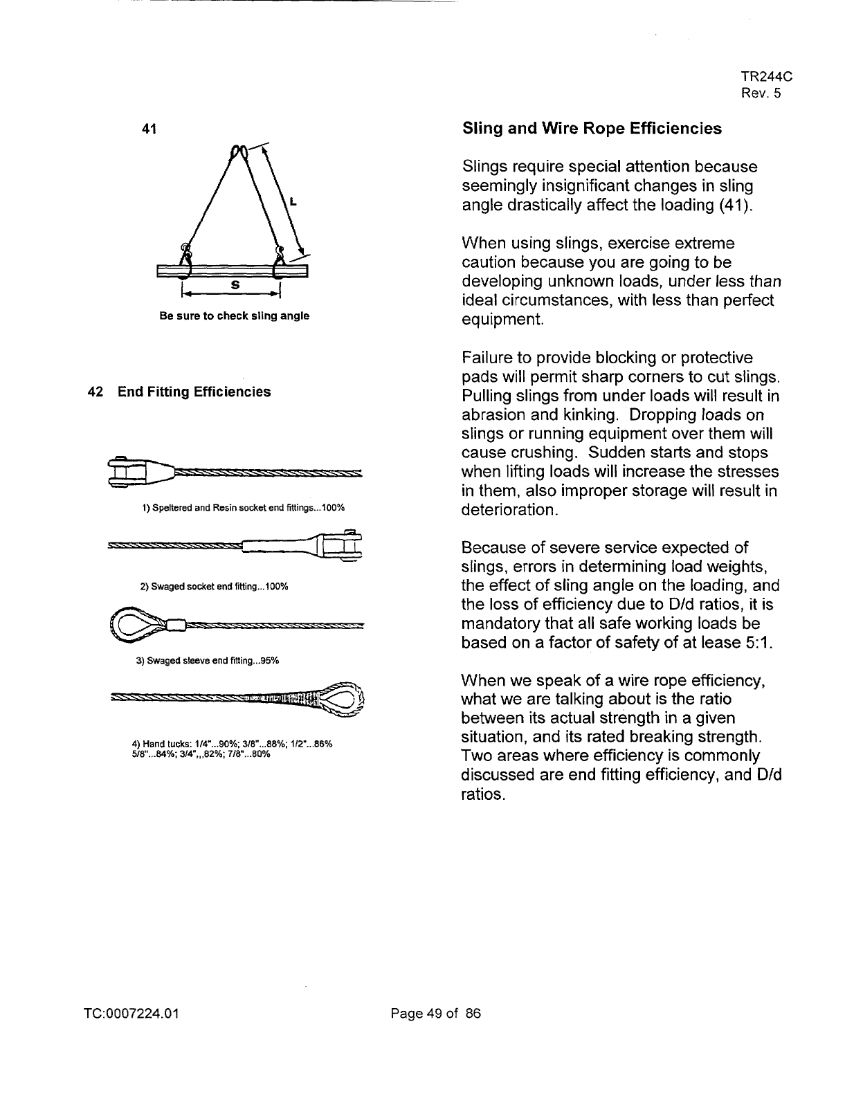
41
Be
sure
to
check
sling angle
42
End Fitting Efficiencies
1) Spekered and
Resin
socket end tiltings
...
100%
n
r
1:
Because of severe service expected
of
L
2)
Swaged
socket
end ftting
...
100%
3)
Swaged
sleeve
end tilting
...
95%
4) Hand
tucks:
114"
...
90%;
318"
...
88%;
112-
...
86%
518".A%;
314",,,a2%;
718"
...
80%
Sling
and
Wire
Rope
Efficiencies
Slings require special attention because
seemingly insignificant changes in sling
angle drastically affect the loading
(41).
When using slings, exercise extreme
caution because you are going to be
developing unknown loads, under less than
ideal circumstances, with less than perfect
equipment.
Failure to provide blocking or protective
pads will permit sharp corners to cut slings.
Pulling slings from under loads will result in
abrasion and kinking. Dropping loads on
slings or running equipment over them will
cause crushing. Sudden starts and stops
when lifting loads will increase the stresses
in them, also improper storage will result in
deterioration.
slings, errors in determining load weights,
the effect of sling angle on the loading, and
the
loss
of efficiency due to D/d ratios, it is
mandatory that all safe working loads be
based on a factor of safety of at lease
51.
When we speak of a wire rope efficiency,
what we are talking about is the ratio
between its actual strength in a given
situation, and its rated breaking strength.
Two areas where efficiency is commonly
discussed are end fitting efficiency, and D/d
ratios.
TC:0007224.01
Page
49
of
86
TR244C
Rev.
5
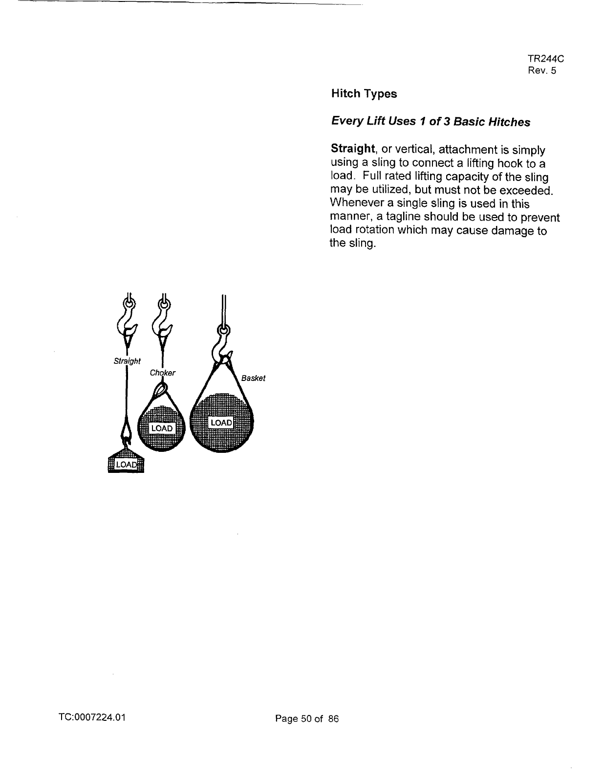
Hitch Types
Every
Lift
Uses
7
of 3 Basic Hitches
Straight,
or vertical, attachment is simply
using a sling
to
connect
a
lifting hook to a
load.
Full
rated lifting capacity
of
the sling
may be utilized, but must not be exceeded.
Whenever a single sling is used
in
this
manner, a tagline should be used to prevent
load rotation
which
may cause damage to
the sling.
QQ
TC:0007224.01
Page
50
of
86
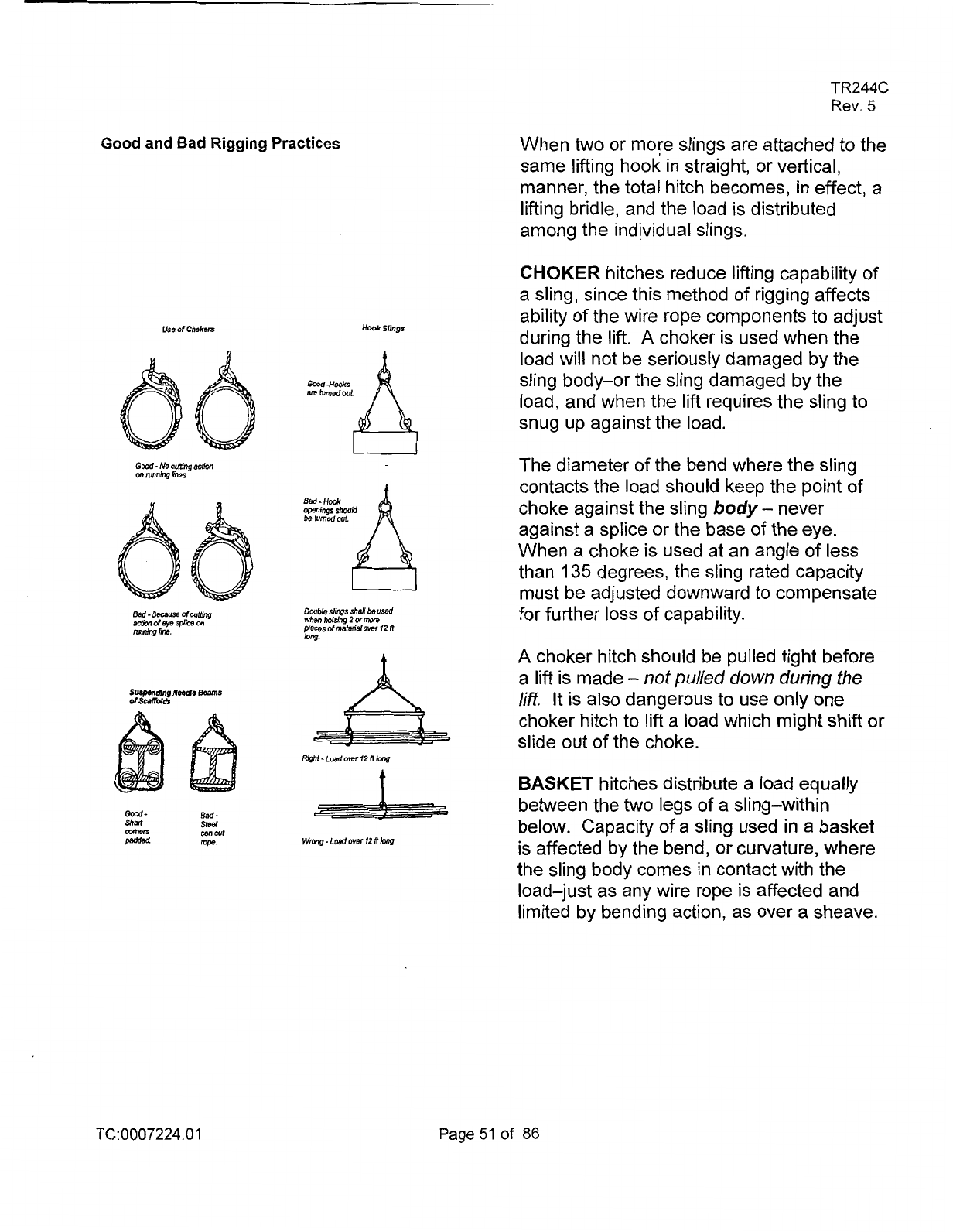
Good
and
Bad
Rigging
Practices
Uss
of
Chdren
Haok
Sfings
t
Bad.
slsel
mail
iwe.
TR244C
Rev.
5
When
two
or more slings are attached to the
same lifting hook in straight, or vertical,
manner, the total hitch becomes, in effect, a
lifting bridle, and the load is distributed
among the individual slings.
CHOKER hitches reduce lifting capability of
a sling, since this method
of
rigging affects
ability of the wire rope components to adjust
during the lift.
A
choker is used when the
load will not be seriously damaged by the
sling body-or the sling damaged by the
load, and when the lift requires the sling to
snug up against the load.
The diameter
of
the bend where the sling
contacts the load should keep the point of
choke against the sling
body
-
never
against a splice or the base
of
the eye.
When a choke is used at an angle
of
less
than
135
degrees, the sling rated capacity
must be adjusted downward to compensate
for further
loss
of
capability.
A
choker hitch should be pulled tight before
a
lift is made
-
not
pulled down during
the
lift.
It
is also dangerous to use only one
choker hitch to lift a load which might
shift
or
slide out of the choke.
BASKET hitches distribute a load equally
between the two legs
of
a sling-within
below. Capacity
of
a sling used in
a
basket
is affected by the bend, or curvature, where
the sling body comes in contact with the
load-just as any wire rope is affected and
limited by bending action, as over a sheave.
TC:0007224.01
Page51
of
86
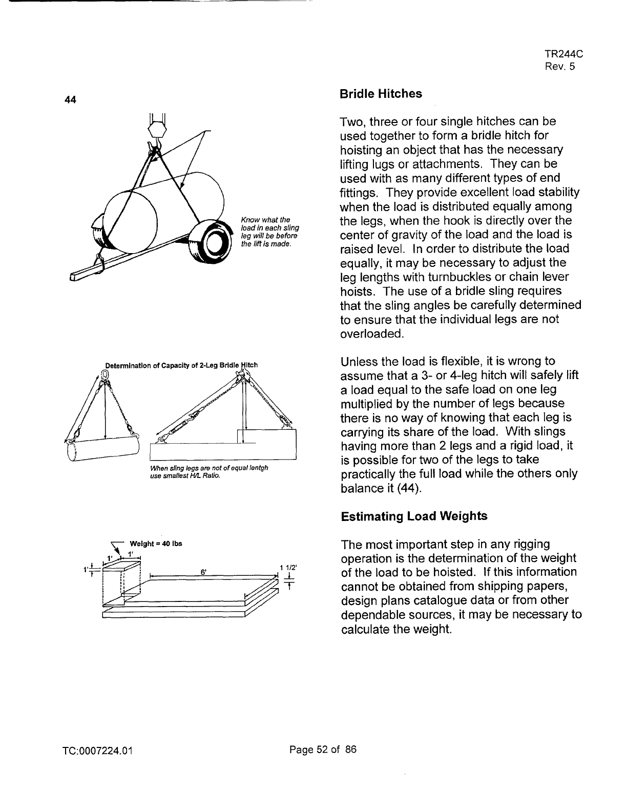
44
TR244C
Rev.
5
Bridle Hitches
Two, three or four single hitches can be
used together to form a bridle hitch for
hoisting an object that has the necessary
lifting lugs or attachments. They can be
used with as many different types of end
fittings. They provide excellent load stability
when the load is distributed equally among
Know
what the
the legs, when the hook is directly over the
load
in
each
sling
leg
will
be before
center of gravity of the load and the load is
the
/iff
is
made.
raised level. In order to distribute the load
equally, it may be necessary to adjust the
leg lengths with turnbuckles or chain lever
hoists. The use of a bridle sling requires
that the sling angles be carefully determined
to ensure that the individual legs are not
overloaded.
Unless the load is flexible,
it
is wrong to
assume that a
3-
or 4-leg hitch will safely lift
a load equal to the safe load on one leg
multiplied by the number of legs because
there is no way of knowing that each leg is
carrying its share of the load. With slings
having more than
2
legs and a rigid load,
it
is possible for two of the legs to take
When ding legs
are
not
of
equal lentgh
use
smallest
HR
Ratio.
practically the full load while the others only
balance
it
(44).
Estimating
Load
Weights
The most important step in any rigging
operation is the determination of the weight
1112’
of the load to be hoisted. If this information
cannot be obtained from shipping papers,
design plans catalogue data or from other
dependable sources, it may be necessary to
calculate the weight.
TC0007224.01
Page52of
86
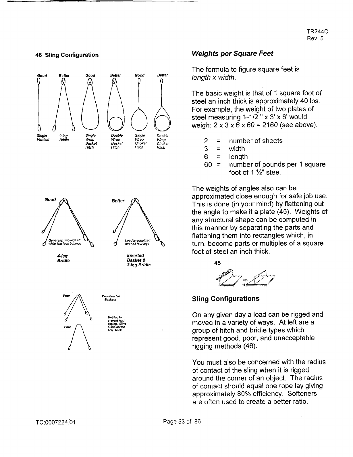
46
Sling Configuration
Single
24eg
Sing/e Double Singje
Vertical Bridle
wrap
wrap
wrap
Basket
Basket Choker
Hitch Hitch Hitch
nerally-
hvo
legs
Ti
Load
is
equalized
'le
hvo
/egs
balance
overall
four
/egs
&leg
Inverted
Bridle Basket
&
24eg Bridle
n
Noming
to
proven;
bad
tipping. Sling
bums
auos
hoist
hook.
TC:0007224
.O
1
TR244C
Rev.
5
Weights
per Square Feet
The formula to figure square feet is
length
x
width.
The basic weight is that of 1 square foot
of
steel an inch thick
is
approximately 40 Ibs.
For example, the weight of
two
plates of
steel measuring 1-112
'I
x
3'
x
6'
would
weigh: 2
x
3
x
6
x
60
=
2160
(see above).
Double
wrap
2
=
number ofsheets
Choker
Hitch
3
=
width
6
=
length
60
=
number of pounds per
1
square
foot of
1
1/21'
steel
The weights of angles also can be
approximated close enough for safe
job
use.
This is done (in your mind) by flattening out
the angle to make
it
a plate (45). Weights
of
any structural shape can be computed in
this manner by separating the parts and
flattening them into rectangles which, in
turn, become parts or multiples of a square
foot of steel an inch thick.
45
Sling
Configurations
On any given day a load can be rigged and
moved in
a
variety
of
ways. At left are a
group of hitch and bridle types which
represent good, poor, and unacceptable
rigging methods
(46).
You must also be concerned with the radius
of contact of the sling when
it
is rigged
around the corner of an object. The radius
of
contact should equal one rope lay giving
approximately
80% efficiency. Softeners
are often used to create a better ratio.
Page53of
86
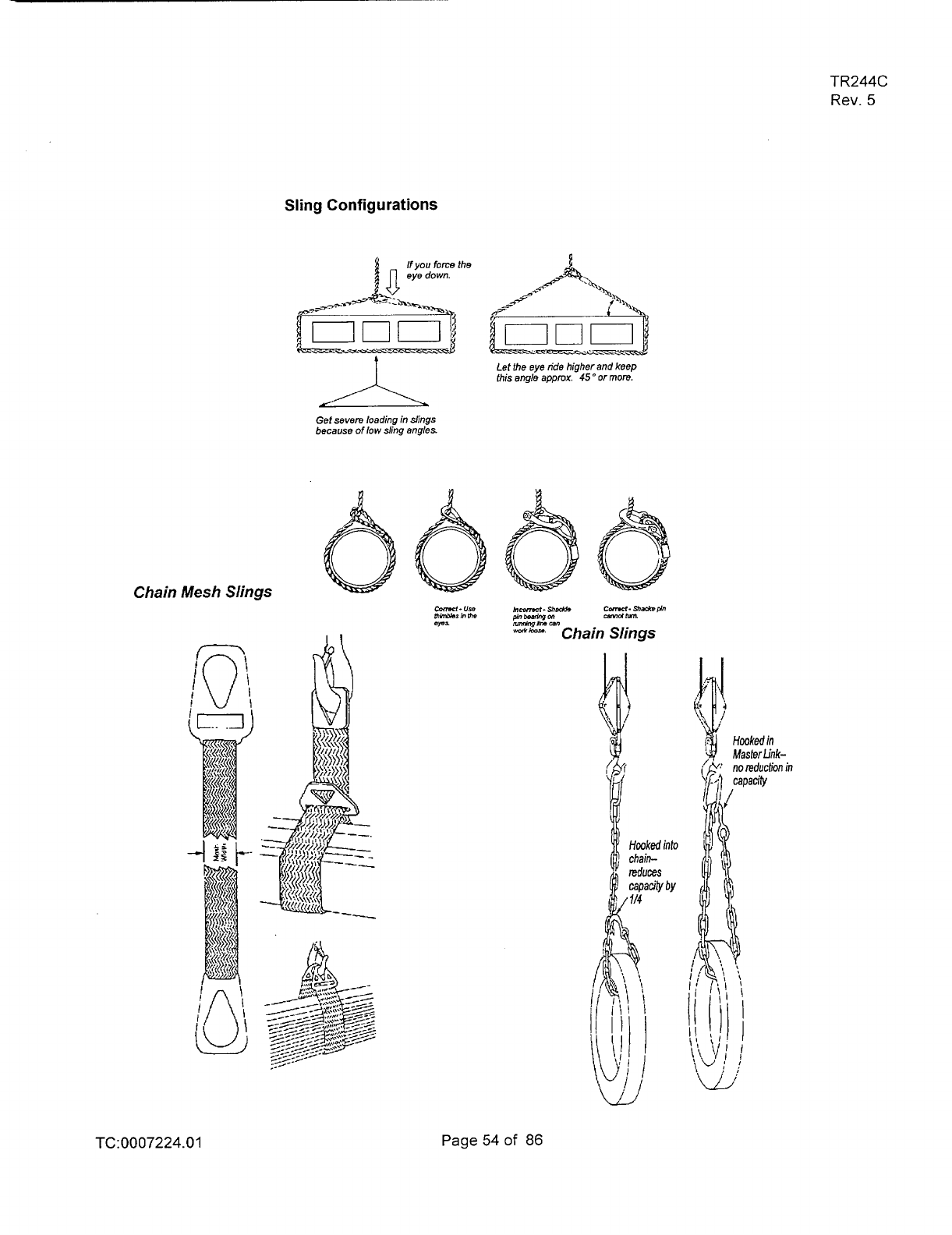
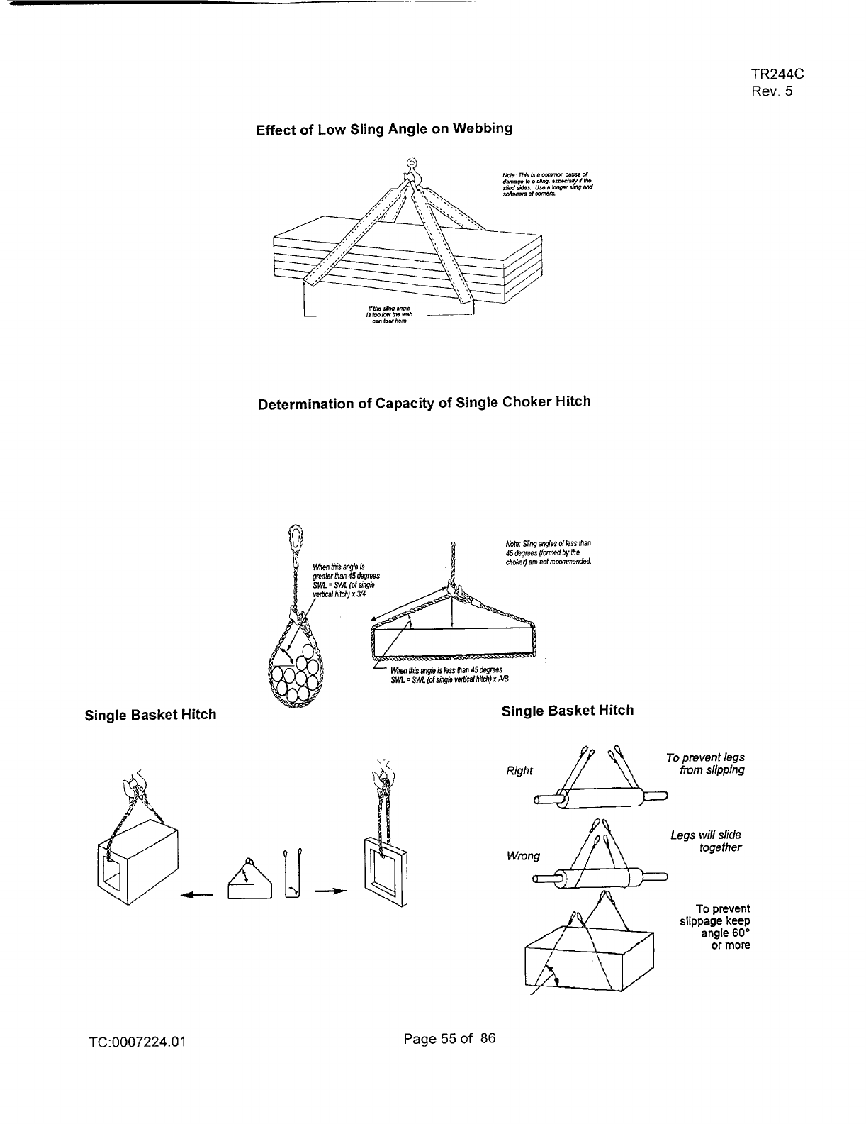
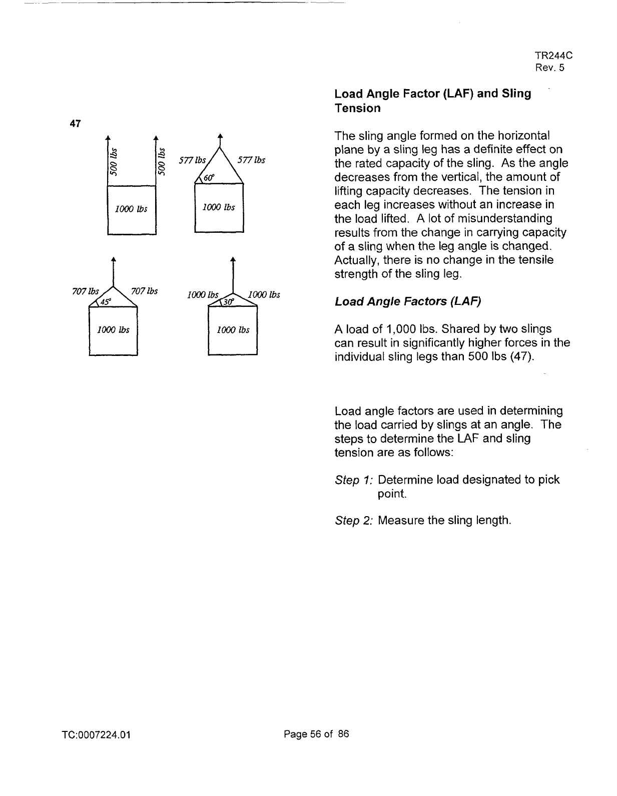
47
8
3
-
5771bs
577
lbs
cr,
8
a
Io00
lbs
IO00
ibs
707
fi
lbs
Ibs
I~~jWOIbs
loa,
ibs
Io00
lbs
TR244C
Rev.
5
Load Angle
Factor
(LAF)
and Sling
Tension
The sling angle formed on the horizontal
plane by a sling leg has a definite effect on
the rated capacity of the sling. As the angle
decreases from the vertical, the amount of
lifting capacity decreases. The tension
in
each leg increases without an increase in
the load lifted. A lot of misunderstanding
results from the change in carrying capacity
of
a sling when the leg angle is changed.
Actually, there is no change in the tensile
strength of the sling leg.
Load
Angle
Factors
(LA
F)
A load of
1,000
Ibs.
Shared by
two
slings
can result in significantly higher forces in the
individual sling legs than
500 Ibs
(47).
Load angle factors are used in determining
the load carried by slings at an angle. The
steps to determine the
LAF
and sling
tension are as follows:
Step
7:
Determine load designated to pick
point.
Step
2: Measure the sling length.
TC:0007224.01
Page56of
86
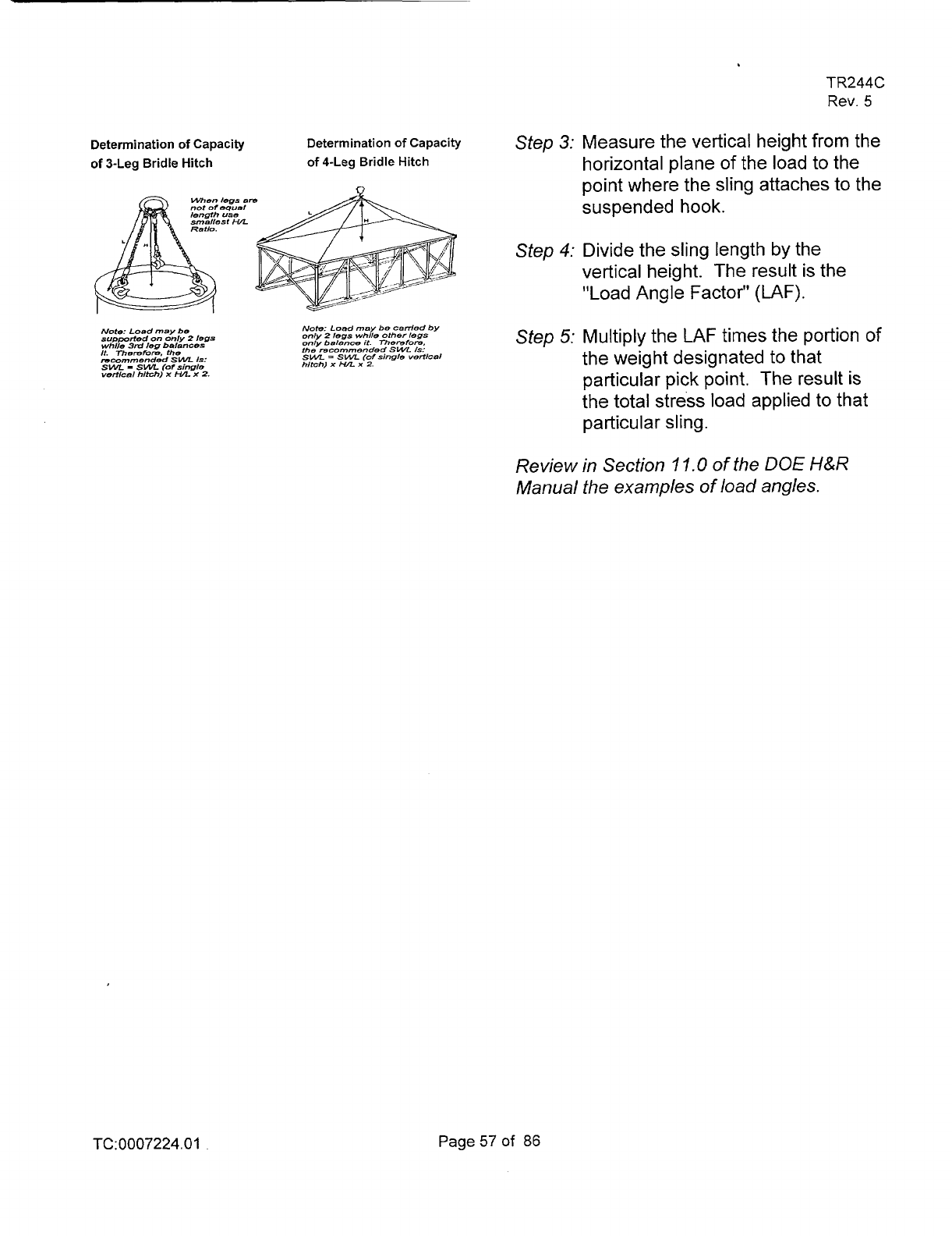
Determinationof Capacity
of
3-Leg Bridle Hitch
When
legs
a
not
or
dguel
length
use
smsllest
HL
Note:
Load
may
be
supported
on
only
2
legs
whlle
3rd
leg
baiances
It.
Theremm,
the
recommended
SWL
Is:
SWL
-
SWL
(or
single
vemcal
hitch)
x
HA
x
2.
Determination
of
Capacity
of
4-Leg Bridle Hitch
Note:
Load
may
be
ceded
by
only
2
legs while other
legs
only
balan-
it.
rnemfore.
the recommended
SWL
/S:
SUR
=
SWL
(of
single
~erticel
hitch)
x
HL
x
2.
TR244C
Rev.
5
Step
3: Measure the vertical height from the
horizontal plane
of the load to the
point where the slina attaches
to
the
-
kuspended hook.
Step
4: Divide the sling length by the
vertical height. The result is the
"Load Angle Factor"
(LAF).
Step
5:
Multiply the
LAF
times the portion
of
the weight designated to that
particular pick point. The result
is
the total stress load applied to that
particular sling.
Review in Section 1
1.0
of
the
DOE
H&R
Manual the examples
of
load
angles.
TC:0007224.01
Page57of
86
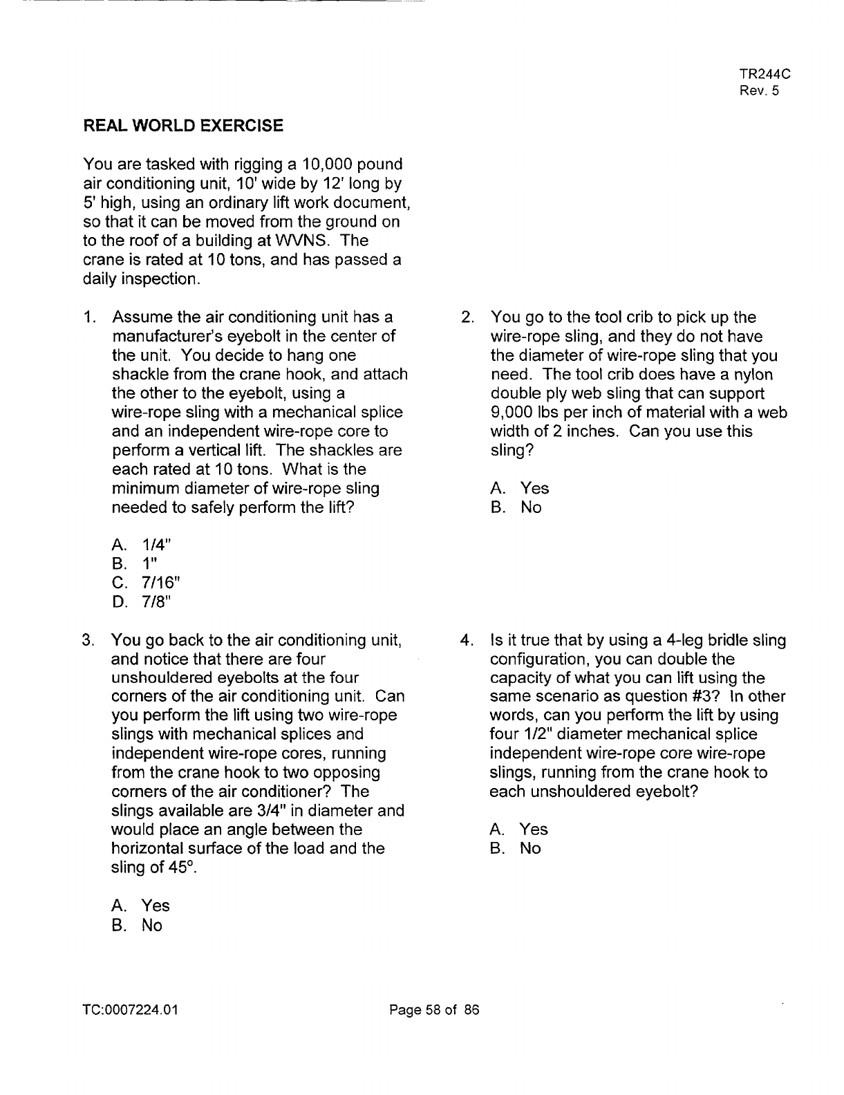
TR244C
Rev.
5
REAL
WORLD
EXERCISE
You are tasked with rigging a 10,000 pound
air conditioning unit,
IO'
wide by
12'
long by
5'
high, using an ordinary
lift
work document,
so
that
it
can be moved from the ground on
to the roof
of
a building at
WVNS.
The
crane is rated at
10 tons, and has passed a
daily inspection.
1.
Assume the air conditioning unit has a
manufacturer's eyebolt in the center of
the unit. You decide to hang one
shackle from the crane hook, and attach
the other to the eyebolt, using a
wire-rope sling with a mechanical splice
and an independent wire-rope core to
perform a vertical
lift.
The shackles are
each rated at 10 tons. What is the
minimum diameter of wire-rope sling
needed to safely perform the
lift?
A. 1/4"
B.
I"
C. 7/16"
D.
7/8"
3. You go back to the air conditioning unit,
and notice that there are four
unshouldered eyebolts at the four
corners of the air conditioning unit. Can
you perform the
lift
using
two
wire-rope
slings with mechanical splices and
independent wire-rope cores, running
from the crane hook to two opposing
corners of the air conditioner? The
slings available are 314" in diameter and
would place an angle between the
horizontal surface of the load and the
sling of 45'.
A.
Yes
B.
No
2.
You go to the tool crib to pick up the
wire-rope sling, and they do not have
the diameter
of
wire-rope sling that you
need. The tool crib does have a nylon
double ply web sling that can support
9,000 Ibs per inch of material with a web
width of
2
inches. Can you use this
sling?
A. Yes
B.
No
4.
Is
it
true that by using
a
4-leg bridle sling
configuration, you can double the
capacity of what you can
lift
using the
same scenario as question
#3?
In
other
words, can you perform the
lift
by using
four 1/2" diameter mechanical splice
independent wire-rope core wire-rope
slings, running from the crane hook to
each unshouldered eyebolt?
A. Yes
B.
No
TC:0007224.0
1
Page58of 86
5.
You decide to increase the angle
between the horizontal surface of the
load and the sling from 45" to 60" by
using
a
six ton spreader beam 12 feet in
length. You attach the spreader beam
to the crane hook, running
it
parallel and
centered along the length of the air
conditioning unit. Two
of
the 1/2"
wire-rope slings will be attached to
hooks on one end of the spreader
beam, running down to the eyebolts,
and two will be attached to the other end
in
a
similar manner. Can you perform
the lift?
A. Yes
B.
No
7.
This means a 10,000 pound air
conditioner would require a shouldered
eyebolt with minimum diameter of?
A.
1/4"
B.
7/8"
C. 34"
D.
I"
E.
11/21'
TR244C
Rev.
5
6. You replace the unshouldered eyebolts
with shouldered eyebolts. At an angle
of 60" between the horizontal surface of
the load and the four 1/2" slings, the
load capacity of the eyebolt is reduced
by:
A.
75%
B.
65%
c.
45%
D.
The load capacity is not reduced.
8.
Is
the overall weight of the air
conditioner divided in
two,
if using two
slings in a two-leg sling configuration at
each end of a spreader beam? In other
words, can
I
use
four 7/16" diameter
mechanical splice independent wire
rope slings in
two
2-leg sling
configurations running from the hooks at
the ends of the 12' spreader beam
to
the shouldered eyebolts, at a
60"
angle
between the horizontal surface
of
the
load and the slings,
if
this configuration
is capable of lifting
5,800 pounds?
A. Yes
B.
No
TC:0007224.01
Page59of
86
TR244C
Rev.
5
9.
Could you
lift,
using a 10 ton crane, a
IO.
Match the rigging component with the
10,000
pound air conditioner,
IO'
wide
by 12' long by
5'
high, with four
shouldered eyebolts
1
1/21!
in diameter
installed at each corner
of
the air
condition, using a
500
pound spreader
beam
12'
in length, attaching the
spreader beam
to
the crane hook,
running
it
parallel and centered along
the length of the air conditioning unit,
with four
7/16"
diameter mechanical
splice independent wire rope slings in
two 2-leg sling configurations running
from the hooks at the ends of the 12'
spreader beam to the shouldered
eyebolts, at
a
60'
angle between the
horizontal surface of the load and the
slings?
A.
Yes
B.
No
appropriate reference page and/or table
from WVDP-082.
A.
Mechanical Splice
(IWRC)
Wire-Rope Slings
B. Spreader Beams
C.
U
n
s
h
o
u Id e red Eye bo Its
D.
Nylon Double Ply Web Slings
supporting
9,000
Ibs per inch of
material
E.
Capacity of a
4
leg bridle hitch
F.
Relationship of load angle and lifting
efficiency
G.
Safe loading of eyebolts
-
shoulder
type only
TC:0007224.01
Page60of
86
TR244C
Rev.
5
REVIEW QUESTIONS
HOISTING AND RIGGING PRACTICES
I.
To
avoid additional stresses, quick
changing
of
the velocity
of
the load
should be performed when hoisting.
A.
True
B.
False
2.
To
control the load, hand contact
should be maintained.
A. True
B.
False
3.
Protectors, softeners and blocking
shall be used at sharp corners.
A. True
B.
False
4.
The inspection tag
is
not requited to
be attached to
sling.
A.
True
B.
False
5.
The weight
of
the load
is
not needed
prior to the
lift.
A.
True
B.
False
6.
High
winds
do
not have any effect on
outdoor
rigging
operations.
A.
True
B.
False
TC:0007224.01
Page62of
86
TR244C
Rev.
5
7.
Loads can be carried or left
suspended over personnel.
A.
True
B.
False
8.
When rigging a load for a high lift,
what precautions should be
observed?
A.
Make all personnel stand clear
B.
rope
off
the area
C.
Never work under a load
D.
All
of
the above
9.
The lifting capacity of
a
synthetic
web sling
is
the same for
a
straight,
choker or basket hitch.
A. True
B.
False
IO.
When using a three or four legged
bridle sling,
the
load
is
carried
equally on each leg.
A.
True
B.
False
11.
High temperatures or very low
temperatures (below
0
degrees
F)
have no effect on wire or synthetic
slings when lifting loads.
A.
True
B.
False
TC:0007224.01
Page63of 86
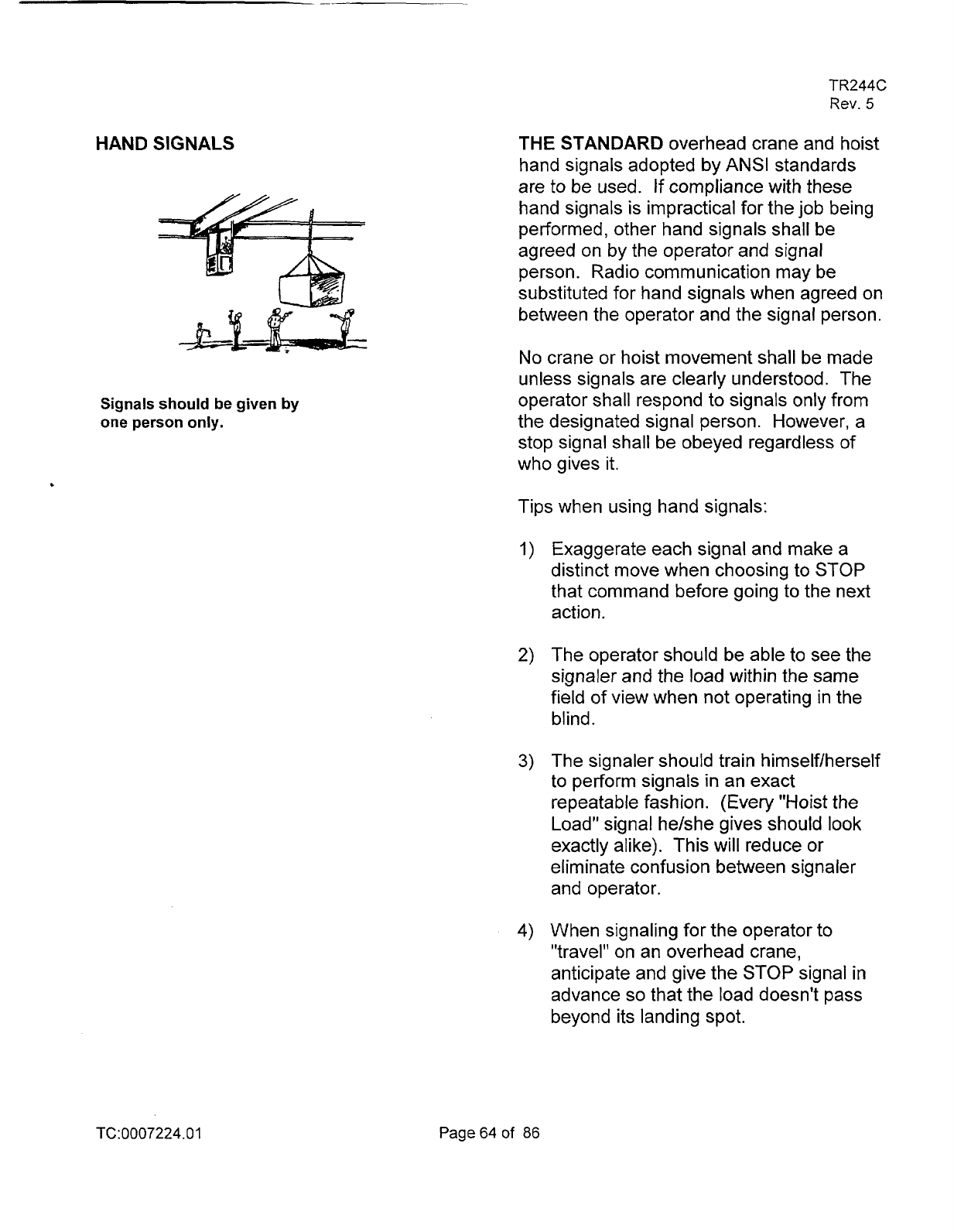
HAND SIGNALS
Signals should be given by
one person only.
TR244C
Rev.
5
THE STANDARD overhead crane and hoist
hand signals adopted by
ANSI
standards
are to be used. If compliance with these
hand signals is impractical for the job being
performed, other hand signals shall be
agreed on by the operator and signal
person. Radio communication may be
substituted for hand signals when agreed on
between the operator and the signal person.
No
crane or hoist movement shall be made
unless signals are clearly understood. The
operator shall respond to signals only from
the designated signal person. However, a
stop signal shall be obeyed regardless
of
who gives it.
Tips when using hand signals:
Exaggerate each signal and make a
distinct move when choosing to STOP
that command before going to the next
action.
The operator should be able to see the
signaler and the load within the same
field of view when not operating in the
blind.
The signaler should train himself/herself
to
perform signals
in
an exact
repeatable fashion. (Every "Hoist the
Load" signal he/she gives should look
exactly alike). This will reduce
or
eliminate confusion between signaler
and operator.
When signaling for the operator to
"travel" on an overhead crane,
anticipate and give the STOP signal in
advance
so
that the load doesn't pass
beyond its landing spot.
TC:0007224.0
1
Page64of
86
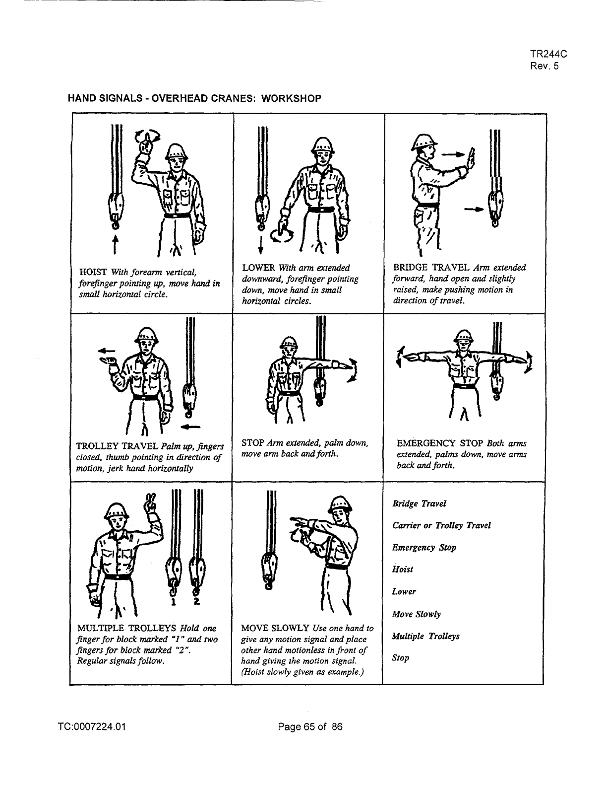
TR244C
Rev.
5
HAND SIGNALS
-
OVERHEAD CRANES: WORKSHOP
HOIST
With forearm vertical,
forefinger pointing
up.
move
hand
in
small
horizontal circle.
lTOLLEY
TRAVEL
Palm
up,
fingers
:lased.
thumb pointing
in
direction of
notion,
jerk
hand
horizontally
MULTIPLE TROLLEYS
Hold
one
finger
for
block marked
“I
*’
and
two
fingers for block marked
“2”.
Regular
signals
follow.
LOWER
With
arm
extended
downward, forefinger pointing
down, move
hand
in
small
horizontal circles.
STOP
Arm
extended, palm down,
move
am
back
and
forth.
MOVE
SLOWLY
Use one hand
to
give
any
motion signal
and
place
other hand motionless
in
front
of
hand
giving
the
motion
signal.
(Hoist slowly given as example.)
BRIDGE
TRAVEL
Ann
extended
forward,
hand
open
and
slightly
raised,
make
pushing
motion
in
direction of travel.
EMERGENCY
STOP
Both arms
extended, palms down, move
am
back
and
forth.
Bridge
Travel
Cam‘er
or
Trolley Travel
Emergency
Stop
Hoist
Lower
Move
Slowly
Multiple
Trolleys
stop
TC:
0007224.0
1
Page
65 of
86
TR244C
Rev.
5
Standard Signals
The standard signals for
DOE
use shall be
as specified in the latest edition of the
American National Standards Institute
(ANSI)
B30
chapters, for the particular type
of
crane or hoist being used.
Identification
of
Signalers
a) All personnel acting as signalers during
crane operations shall be clearly
identified to the crane operator by the
use of the following (one or more, as
required by the cognizant manager):
orange hardhat; orange gloves; and/or
orange vest. At
WVNS,
riggers are
required to wear orange vests when
lifting outside. Additionally, the orange
rain coat used during inclement weather
may be used in lieu of the orange vest.
Also, a hat or orange gloves must be
used by the signaler(s) for identification
purposes. This requirement may be
waived by the cognizant manager when
the lift is very closely controlled or
personnel are required to wear special
clothing for protection from a hazardous
environment.
b) In those cases where the crane operator
cannot see the signaler, a second
person (relay signaler) shall be
stationed where he/she can see both
the signaler and the crane operator and
relay the signals to the operator.
TC:0007224.01
Page66of
86
TR244C
Rev.
5
c) Where voice (direct or two-way radio)
communication is used, the signaler
shall communicate directly with the
operator: not through
a
third person.
d) The operator
shall
recognize signals
only from the designated signaler,
except that a signal for a stop shall be
obeyed when given by anyone.
TC:0007224.01
Page67of 86

TR244C
Rev.
5
INCIDENTAL HOISTING OPERATOR
KNOWLEDGE OBJECTIVES
OBJECTIVES
0
State the qualification requirements for
incidental crane operators.
0
Identify the main components
of the
hoist and crane.
0
Explain what inspection should be
performed on the equipment prior to
use.
Describe the hand signals used during
lifting operations.
0
Explain what a side pull is and how it is
possible to damage equipment.
0
Explain what safe working practices to
consider when using hoists and cranes.
TC:0007224.0
1
Page68of
86
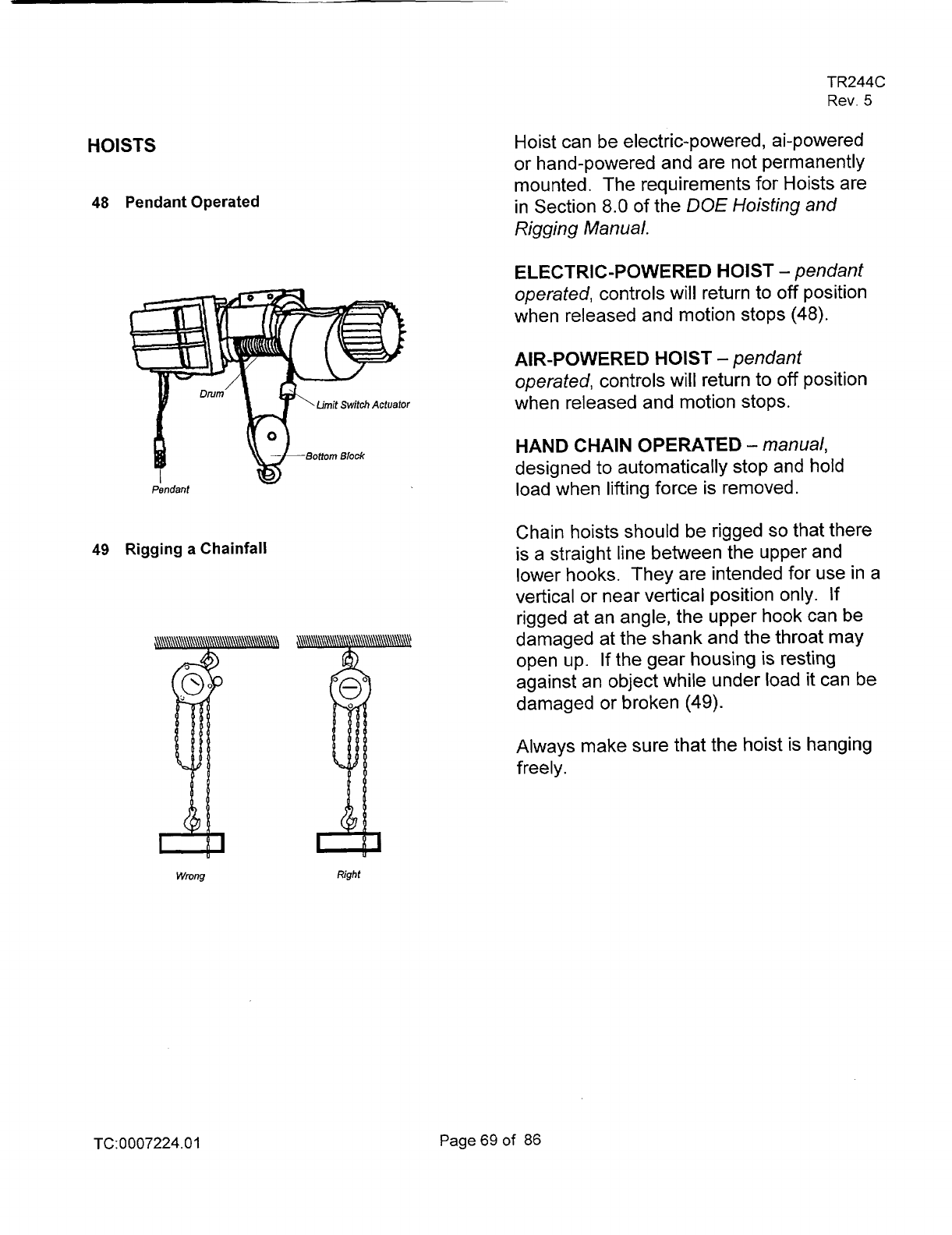
HOISTS
48
Pendant Operated
49
Rigging
a
Chainfall
Wrung
Right
TR244C
Rev.
5
Hoist can be electric-powered, ai-powered
or hand-powered and are not permanently
mounted. The requirements for Hoists are
in Section
8.0
of
the
DOE
Hoisting and
Rigging Manual.
ELECTRIC-POWERED
HOIST
-
pendant
operated,
controls will return to
off
position
when released and motion stops
(48).
AIR-POWERED HOIST
-
pendant
operated,
controls will return to
off
position
when released and motion stops.
HAND CHAIN OPERATED
-
manual,
designed to automatically stop and hold
load when lifting force is removed.
Chain hoists should be rigged
so
that there
is a straight line between the upper and
lower hooks. They are intended for use in a
vertical or near vertical position only. If
rigged at an angle, the upper hook can be
damaged at the shank and the throat may
open up.
If
the gear housing is resting
against an object while under load
it
can be
damaged or broken
(49).
Always make sure that the hoist is hanging
freely.
TC: 0007224.0
1
Page
69 of
86
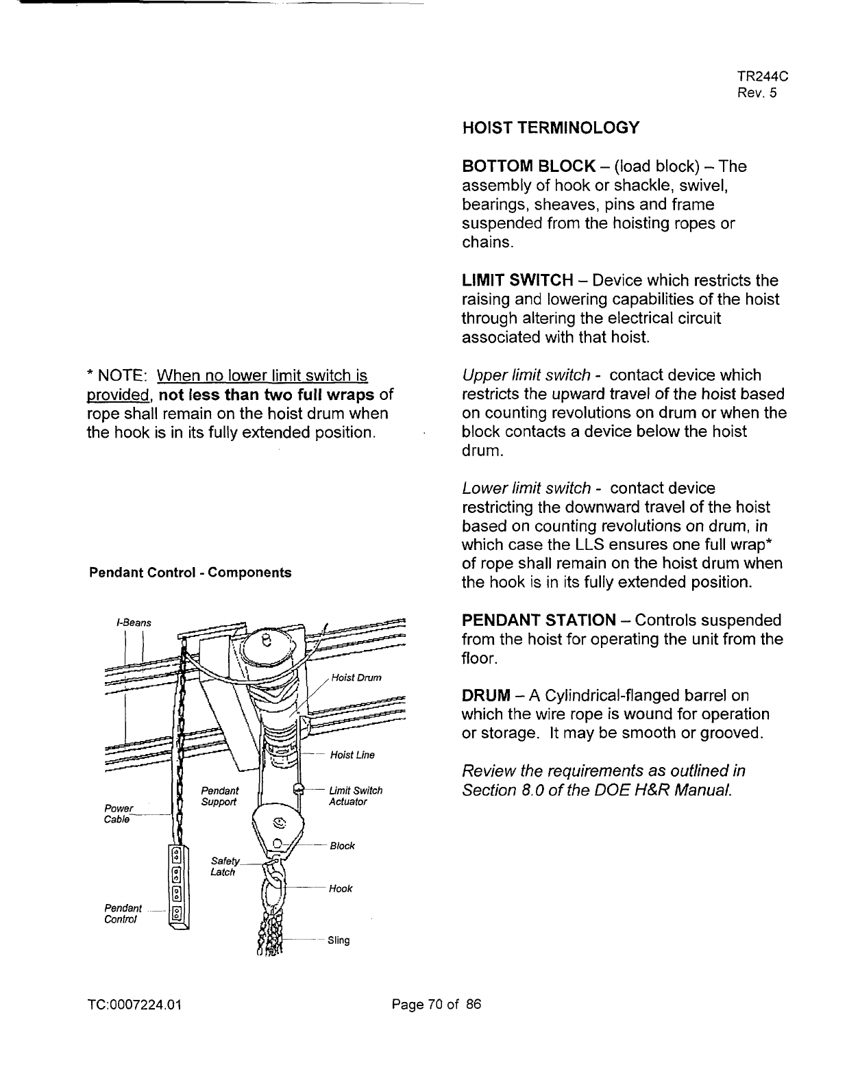
*
NOTE: When no lower limit switch is
provided,
not
less
than
two
full
wraps
of
rope shall remain on the hoist drum when
.
the hook
is
in its fully extended position.
Pendant Control
-
Components
TR244C
Rev.
5
HOIST TERMINOLOGY
BOTTOM BLOCK
-
(load block)
-
The
assembly of hook or shackle, swivel,
bearings, sheaves, pins and frame
suspended from the hoisting ropes or
chains.
LIMIT SWITCH
-
Device which restricts the
raising and lowering capabilities of the hoist
through altering the electrical circuit
associated with that hoist.
Upper limit switch
-
contact device which
restricts the upward travel of the hoist based
on counting revolutions on drum or when the
block contacts a device below the hoist
drum.
Lower limit switch
-
contact device
restricting the downward travel of the hoist
based on counting revolutions on drum, in
which case the
LLS
ensures one full wrap*
of
rope shall remain on the hoist drum when
the hook is in its fully extended position.
PENDANT STATION
-
Controls suspended
from the hoist for operating the unit from the
floor.
DRUM
-A
Cylindrical-flanged barrel on
which the wire rope is wound for operation
or storage.
It
may be smooth or grooved.
Review the requirements
as
outlined in
Secfion
8.0
of
the DOE
H&R
Manual.
TC: 0007224.0
1
Page70of
86
TR244C
Rev.
5
OVERHEADANDGANTRYCRANES
The larger cranes are mostly
of
the
overhead
type controlled by a pendant
which hangs from the crane. The pendent
controls the hoist motion and bridge and
trolley travel.
The various types
of
cranes are described in
Section 7.0
of
the
DOE
Hoisting and
Rigging Manual.
Review Section
7.0,
"Overhead and Gantry
Cranes" in the
DOE
H&R Manual.
The inspection criteria is outlined in
SOP
15-56, "Inspection Mechanized
Hoisting Equipment." Each crane is
inspected monthly
by
maintenance and is
noted on the inspection tag.
TC:0007224.01
Page71
of
86
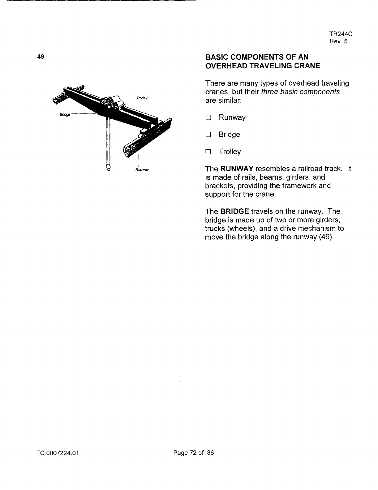
49
TR244C
Rev.
5
BASIC COMPONENTS
OF
AN
OVERHEAD TRAVELING CRANE
There are many types
of
overhead traveling
cranes, but their
three basic components
are similar:
17
Runway
0
Bridge
0
Trolley
I
Runwav
The RUNWAY resembles a railroad track. It
is made
of
rails, beams, girders, and
brackets, providing the framework and
support for the crane.
The BRIDGE travels on the runway. The
bridge is made up of
two
or more girders,
trucks (wheels), and a drive mechanism
to
move the bridge along the runway (49).
TC:0007224.01
Page72of 86
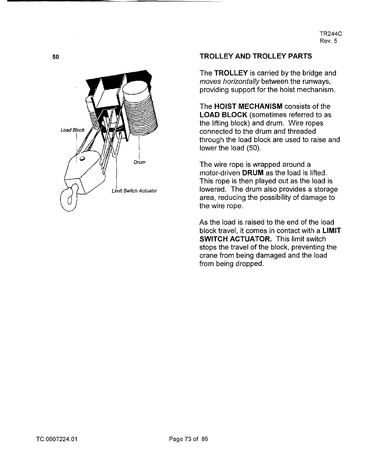
50
TR244C
Rev.
5
TROLLEY AND TROLLEY PARTS
The TROLLEY is carried by the bridge and
moves
horizontally
between the runways,
providing support for the hoist mechanism.
The HOIST MECHANISM consists of the
LOAD BLOCK (sometimes referred to as
the lifting block) and drum. Wire ropes
connected to the drum and threaded
through the load block are used to raise and
lower the load
(50).
The wire rope is wrapped around a
motor-driven DRUM as the load is lifted.
This rope is then played out as the load
is
lowered. The drum also provides a storage
area, reducing the possibility of damage to
the wire rope.
As
the load
is
raised to the end of the load
block travel,
it
comes
in
contact with a LIMIT
SWITCH ACTUATOR. This limit switch
stops the travel
of the block, preventing the
crane from being damaged and the load
from being dropped.
TC:0007224.0
1
Page73of
86
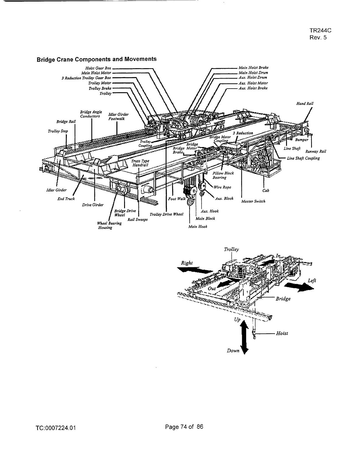
TR244C
Rev.
5
Bridge
Crane Components
and
Movements
Hoist Gear
Box
Main
Hoist
Brake
Main
Hoist Motor
Main
Hoist
Drum
3
Reduction
Trollq
Gear
Bar
Aw.
Hoist
Drum
Aur.
Hoist
Mofor
Awc.
Hoist
Brake
Howing
Trolley
Line Shaft
Coupling
TC:0007224.0
1
Page74of
86
TR244C
Rev.
5
REVIEW QUESTIONS
HOISTS AND OVERHEAD CRANES
1.
A hoist wire rope can be used as
a
ground for welding.
A.
True
B.
False
2.
The hoist wire rope or chain can be
used to wrap around the load for a
I
ift.
A. True
B.
False
3.
All
controls shall be tested by
the
operator prior to operation of the
hoist or crane
at
the beginning of the
shift.
A.
True
B.
False
4.
When there
is
any question as to the
safety
of
the activity, the crane
operator has the authority to stop or
refuse to handle loads.
A.
True
B.
False
5.
To avoid
a
side pull, the hook should
be centered over the center
of
gravity
of the load.
A.
True
B.
False
TC:0007224.0
1
Page75of
86
TR244C
Rev.
5
6.
SOP
15-56
What personal protection equipment
is required to be worn when
conducting or observing
a
load test.
A. Shoes
B. Hard hat
C.
Glasses
D.
Safety glasses, steel toe shoes and
hard hat
7.
SOP 15-56
Prior to use
of
the hoist or crane each
day
the operator shall perform
a
daily
check
of
the equipment.
A. True
B. False
8. SOP 15-56
Daily check by
the
operator will
include:
A. Brakes, control mechanism, hoist
rope
B. Warning device, lights, guards
C.
Safety devices
D. All
of the above
9.
If
a
load becomes unbalanced, lower
and rebalance the load,
it
should not
be lifted more than
a
few inches until
it
is
properly balanced.
A. True
B. False
IO.
When a lower-limit device
is
not
provided, the loaded hoist drum
shall
not be rotated
in
the lowering
direction beyond how many wire-
rope wraps on the drum.
A. One-Half
B. One
C.
Four
D.
Two
1
I.
The hoist-limit switch which controls
the upper limit
of
travel
of
the load
block shall never be used as a
normal operation control.
A. True
B. False
12. Matching
-
Fill in the blanks with the
correct letter next to the proper
d esc
ri
pti
o
n
:
-
Main Block
-
Bridge Rail
-
Rail Sweeps
-
Bumper
-
Trolley
-
Trolley Stop
-
Aux.
Block
-
Runway Rail
-
Bridge Drive Wheel
TC:0007224.01
Page76of 86
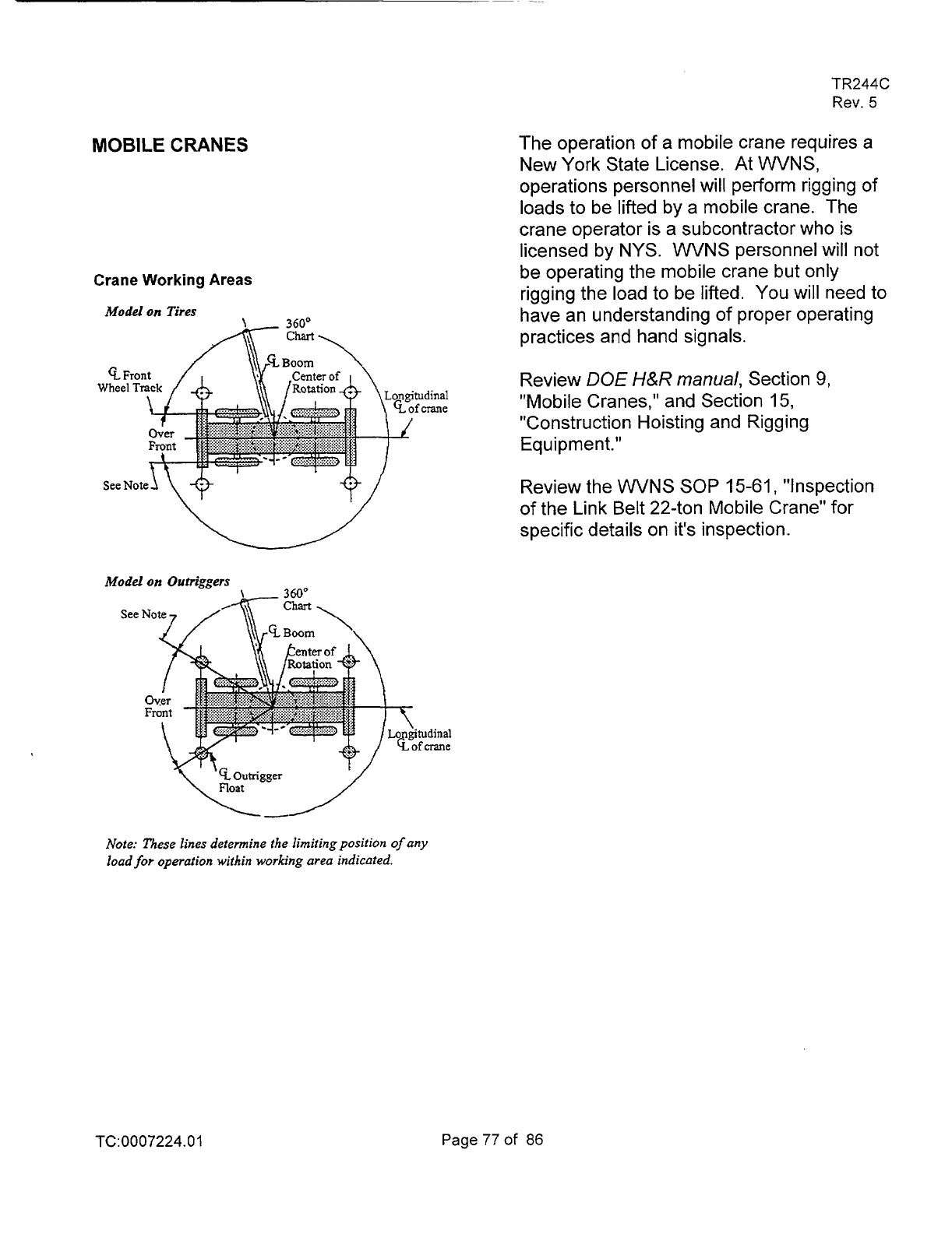
MOBILE
CRANES
Crane Working Areas
M
x)
gitudinal
Eofcrane
Note: These lines determine the limitingposition
of
any
load
for
operation within working area indicated.
TR244C
Rev.
5
The operation
of
a mobile crane requires a
New York State License. At
WVNS,
operations personnel will perform rigging of
loads to be lifted by a mobile crane. The
crane operator is a subcontractor who
is
licensed by NYS.
WVNS
personnel will not
be operating the mobile crane but only
rigging the load to be lifted.
You
will need to
have an understanding of proper operating
practices and hand signals.
Review
DOE
H&R
manual,
Section
9,
"Mobile Cranes," and Section
15,
"Construction Hoisting and Rigging
Equipment."
Review the
WVNS SOP
15-61,
"Inspection
of the Link Belt 22-ton Mobile Crane" for
specific details on it's inspection.
TC:0007224.01
Page77of
86

CRANE TIPS WHILE LIFTING LOAD
AT
HANFORD
On May
30,
1997, at the Hanford Tank
Farms, a 30-ton mobile, hydraulic crane
lifting a 4,600-pound steel trench box tipped,
and the boom landed on a 10-foot mound of
dirt. The crane came to rest against the
mound at a 45-degree angle. The crane
operator and an assisting flagman were not
injured. Investigators determined that the
crane operator failed to extend all four
outriggers as required for this type of lift.
Loss
of control of the crane could have
caused equipment damage or personal
injury. (RL-PHMC-TANKFARM-1997-0048)
A subcontractor had excavated a trench and
shored it with the steel trench boxes and
stacked them for removal. Investigators
determined that the operator extended the
front
two
outriggers
of
the crane, but failed
to extend the rear
two,
when preparing to lift
the sections. A typical hydraulic crane,
displaying the outrigger configuration, is
shown in Figure 4-1.
TR244C
Rev.
5
The operator picked up the load and
extended the boom. As he rotated the load
to the side
of
the crane, the crane fell
against the mound of dirt (see Figure 4-2).
The operator shut down
the
crane and
exited without injury.
Investigators determined that the load rating
chart for the crane permitted
lifts
without
extended outriggers. However, the
allowable load, boom angle, and extension
are greatly reduced. The load chart does
not address operating the crane with only
two outriggers extended. According to the
load chart, the capacity and geometry of the
lift were acceptable with all outriggers
extended. Investigators determined that the
crane operator failed to properly configure
the crane for the lift.
TC:0007224.01
Page78of 86
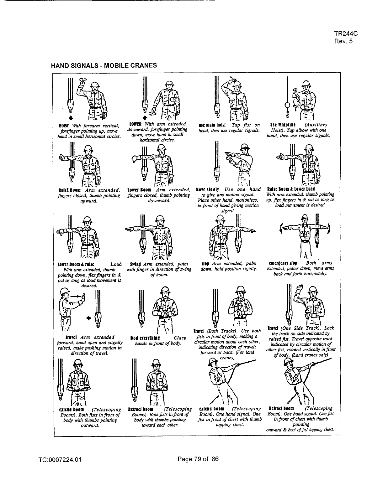
TR244C
Rev.
5
HAND
SIGNALS
-
MOBILE
CRANES
PaiSE
BOOW
Arm-
extended,
fingers closed, thumb pointing
upward.
Lower BOOD
&
JOISC
Load
Wth
arm
extende&
thumb
pointing
down,
flex
fingers
in
&
out
as
long
as
load
movement
is
desired.
frarel
Arm extended
forward.
had
open
and
slightiy
raised,
make
pushing motion in
direcrion
of
travel.
.
.
cxlc~l
boom
(Telescoping
Booms). Both
fits
in
from
of
body
with
thumbs
pointing
outward.
Lowcr
Boom
Arm extended,
fingers closed, thumb poinring
downward.
SWiDg
Arm
..
extended, point
with finger in direction ofnVing
of boom.
I
n
Pclracf
boom
(Telescoping
Booms).
Bothfisrs
infront
of
body
with
lhwnbs
pointing
wwmd each
other.
HOPC
sl@WlY
Use one hand
to
give
any
motion
signal.
Place other
hand,
motionless,
in front
of
hand giving motion
signal.
$ID)
Arm extended, palm
down,
hold
position rigidly.
I
hwd
(Boih Tracks). Use both
CXlCDa
bOOD
(Telescoping
Boom).
One
hand signal.
One
$st
in
from
of
chest with thumb
tapping chest
Use
Whiplinc
(Auxiliary
Hoist).
Tap
elbow
with
one
hand,
then use regular signals.
Ralrr
BOOD
is
~owcrioa~i
Wth
arm
extended,
thumb
pointing
up,
fIer
fingers
in
&
out
as
long
as
Iwd
movement
is
desired.
cmcr&aq
slop
Both
arms
&ended, pdms down, move
anns
back
and
forth
horiz~nfally.
rralcl
(One
Side
Track). Lock
the
track
on
side
indicated
by
raised
fisr.
Travel opposite
track
indicated
by
circular
morion of
other
fist.
rotated vem*&
in
ftont
Rclrarl
bO@m
..
(Telescoping
Boom).
One
hand
signal.
One
fit
in
front
of
chest
with
M
poiming
ommld
&
heel
offin
topping
chest.
TC:0007224.01
Page79of
86
TR244C
Rev.
5
REVIEW QUESTIONS
MOBILE
CRANES
1.
Load can be moved over personnel
in
the hoisting area.
A. True
B.
False
2.
Work can be conducted under
suspended loads under normal
conditions.
A. True
B.
False
3.
To reduce the load swinging when
lifted the hook should be positioned
over the center
of
gravity
of
the load.
A.
True
B.
False
4.
An ordinary
lift
with
more than one
person requires a designated leader.
A.
True
B.
False
5.
A person-in-charge
(PIC)
is
required
for
a
critical
lift.
A.
True
B.
False
TC:0007224.01
Page80of 86
TR244C
Rev.
5
APPENDIX SUBCONTRACTOR EMPLOYEE FATALLY
INJURED IN TANK MOVING OPERATION
On November 14, 1992, an employee
of
Chemical Waste Management, Inc.
(CWM)
was critically injured when one of the
two
straps around a tank being lifted failed,
allowing the tank to fall and strike the
employee. The employee died as a result
of
those injuries on November 19, 1992. This
incident occurred at the Oak Ridge
K-25
Site in Oak Ridge, Tennessee.
Following is a summary
of
the direct,
primary and secondary contributing and root
causes as described in the Type
A
Investigation
of
the accident, which was
carried out at the direction
of
the
DOE
Oak
Ridge Field Office.
Also included are
lessons learned, and comparisons of
potential situations at the West Valley
Demonstration Project.
The details of the accident, root causes and
lessons learned should be discussed at all
operations groups workplace meetings.
All
hands should be reminded that they are
empowered, and directed, to stop any jobs
they believe are unsafe, and bring the
conditions to the attention of their supervisor
for correction.
TC:0007224.01
Page
81
of 86
TR244C
Rev.
5
Accident Description
Con trib
u
ting Causes
(primary)
On Friday, November 13, 1992,
two
6800-gallon polyethylene tanks arrived at
the Pond Waste Management Project
(PWMP
-
part of the
K-25
Site), were
off-loaded from the delivery truck by forklift,
and were rolled into the work area by hand.
The next day (Saturday), preparations
began for lifting the first of the
two
tanks into
a bermed area for installation. The lower
ends of
two
synthetic lifting slings were
shackled to
two
synthetic tie-down straps
encircling the tank. The upper ends of the
two
slings were then attached via a third
synthetic sling to one time of an
extendable-boom "Skytrak" (trade name)
forklift
As the tank was being lifted by the
Skytrak into the berm, several of the
workers, including the accident victim,
moved into the berm to position the tank.
As
the tank was passing over the berm wall,
one of the tie-down straps failed at a
preexisting flaw. The tank fell, struck the
berm wall, bounded into the berm, and
struck the victim, injuring him. He died five
days later.
Findings
of
the DOE Investigation
Direct Cause:
The direct cause
of
the accident was
determined to be the failure
of
the tie-down
strap used to rig the storage tank for lifting.
(The inappropriate use of the tie-down strap
for lifting is discussed in detail under
contributing causes.)
1.
The Rigging Equipment Selected Was
Improper:
Two 2-inch tie-down straps
were used as lifting slings around the
tank. It was determined during the
investigation that the strap that failed
had a preexisting
.6"
cut, and it was at
this point that it failed.
A
boomed forklift
was used to hoist the tank, but the
manufacturer's specifications state it is
not to be used in that type of application
("DO
NOT travel or turn with the boom
up."
To
hoist the tanks into place, the
Skytrak was required to travel with the
boom in an elevated and extended
position. The tag on the failed tie-down
strap was marked, "This tie-down
assembly is not to be used for lifting,"
The lifting slings which were used to rig
the tank to the forklift did not have
legible tags.
2.
Personnel Were Not Separated in
Space From
the
Suspended Load:
Tag
lines were not used to assist in
maneuvering the load. Five employees
were inside the bermed area where the
tank was being placed, and were in
close proximity to the load. The victim
was less than seven feet away.
3.
Tie-Down Straps Were Deteriorated and
Flawed:
The strap which failed was
found to have
a
preexisting flaw of
.6
inches which was found, through
laboratory testing of similar straps, to
have reduced
its tensile strength to
2350 pounds. Investigators calculated
that the tensile load on the failed strap
was
2370
pounds (dynamic forces were
not considered in this calculation).
Witnesses stated that one of the straps
had a preexisting flaw, but it was used in
spite of that fact.
TC:0007224.01
Page82of
86

4.
5.
6,
Lines
of
Supervision Were Not
Clear.
The subcontractor operational chain of
command differed significantly from the
formal organization chart. There was
considerable confusion regarding who
was directing the tank moving operation.
On-the-Job Hazard Recognition Was
Less Than Adequate (LTA):
The actual
weight of the tank was not known.
Tie-down straps were used instead of
slings. Employees were allowed to be
too close to a suspended load.
Employees did not realize that
approximately 150 gallons of water
remaining in the tank from a static lead
test added approximately
1
180 pounds
to the weight of the tank. Subcontractor
(CWM) management did not expect line
supervision to look for or identify job and
safety hazards.
Hazard Underestimated by
Subcontractor Management:
There was
not specific pre-job briefing held prior to
the tank moving operation. There was
not single person-in-charge (PIC).
Employees involved in the operation
each had a different understanding of
the lifting sequence. The forklift
operator did not see the workers enter
the berm under the suspended load.
Three of the five workers in the berm did
not attend the morning safety briefing.
In fact, the morning safety briefing DID
NOT COVER any of the days scheduled
work, including the tank moving
operation. Site safety personnel were
not aware of the operation. No
subcontractor safety personnel were
present during the moving operation.
TR244C
Rev.
5
Responsible subcontractor managers
were not on-site that day (Saturday).
WORKERS WHO WERE NOT
TRAINED
IN HOISTING AND RIGGING
WERE ASSIGNED TO THE JOB.
7.
Work Controls Were
LTA:
There was
not a proper work document for the
operation; only a "maintenance work
order" with a short narrative description
and hand-drawn sketches. This
maintenance work order included no
procedure, safety precautions,
acceptance criteria
, quality assurance ,
or signature for acceptance by the
customer. The sketches provided were
not sufficient to complete the job and
had to be supplemented by oral
instructions at the
job
site.
8.
Roles and Responsibilities Were
Not
Understood by Employees:
Employees
at the job site did not clearly understand
who was in charge of directing the tank
movement operation, and who decided
to use the tie-down straps for rigging.
Personnel involved with the job did not
receive any pre-job briefing;
consequently, the workers did not
understand what task they were to
perform.
There was a total
of three subcontractor
companies involved in the tank
operation: Chemical Waste
Management, Inc. (CWM), Rust
International Corporation (Rust), and
Veterans Steel Erection Co. (Veterans).
THE RESPONSIBILITY FOR RIGGING
AND MOVING THE TANK RESTED
WITH VETERANS. The Veterans
employees stated that they were there
to assist CWM in placing the tank.
CWM
employees stated they were there
to assist Veterans with placement of the
tank.
TC:0007224.01
Page83of
86
9.
Schedule pressure emphasized
production:
Workers stated there was
enormous pressure to meet critical
deadlines (driven by regulatory
agencies). The subcontractor (CWM)
was working on a seven-day work week,
and workers averaged over
50
hours of
overtime per two-week pay period. It
was widely believed that, if the schedule
was missed, the subcontractor would
lose future opportunities for additional
contracts at Oak Ridge.
10.
Subcontractor Project Planning and
Management Were
LTA:
The CWM
weekend work activities were normally
planned at a Wednesday morning
meeting. The tanks were delivered late
on Friday, and subsequently, the tank
moving operation was not included on
the published schedule. Other than the
inadequate "maintenance work
document," all work instructions were
given orally. CWM management did not
emphasize safety over production
schedules.
TC:0007224.01
Page84of
86
TR244C
Rev.
5
TR244C
Rev.
5
ANSWER KEY
OPERATOR TRAINING AND
QUALIFICATIONS
Wire Rope Sling
I.
A
2.
B
3.
B
4.
c
Synthetic Web Sling
1.
B
2. D
3.
B
4.
B
Chain Slings
I.
A
2.
B
3.
A
Spreader Beams
1.
B
2.
B
3.
A
Rigging Hardware
1.
A
2.
A
3.
A
4.
A
5.
B
6.
A
7.
A
8.
A
9.
A
IO.
A
11.
A
12.
A
13.
B
14.
A
15.
D
TC:0007224.0
1
Page85of
86

Critical
Lift
1.
Reference Page 40.
2.
A
3.
Reference Page 41.
General Rigging Practices
I.
B
2.
B
3.
A
4.
B
5.
B
6.
B
7.
B
8.
D
9.
B
10.
B
11.
B
TR244C
Rev.
5
Hoists and Overhead Cranes
I.
B
2.
B
3.
A
4. A
5.
A
6.
D
7.
A
8.
D
9.
A
IO.
D
11.
A
12.
F,
B,
E,
I,
A,
C,
GI
H,
D
Mobile Cranes
1.
B
2.
B
3.
A
4.
A
5.
A
TC:0007224.01
Page86of 86
