Foreword
and F.A.Q.
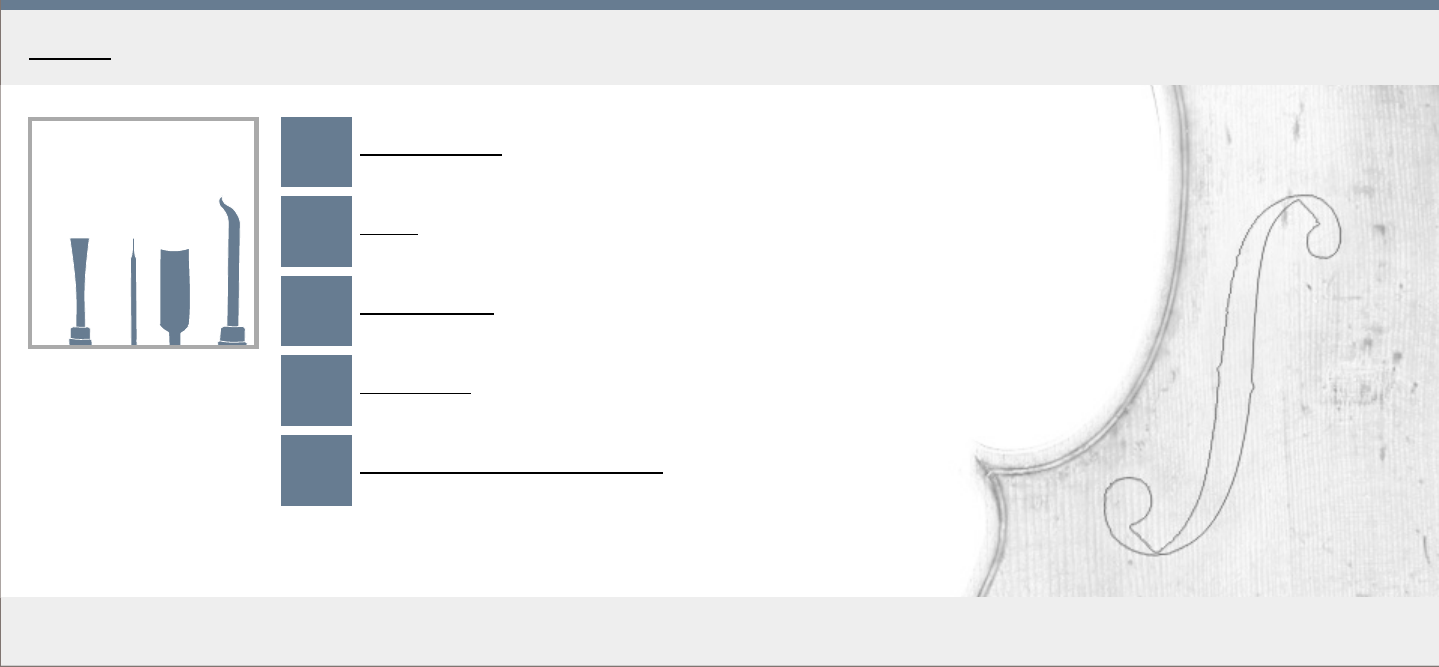
Tools &
materials
An to ni o St ra di va ri
Th e Me ss ia h
17 16
Templates Mould &
blocks
Ribs
a
d
c
Front
4.2
3.6
3.5
2.6
2.8
2.7
3.1
2.6
2.6
2.6
2.5
2.5
3.0
2.9
3.1
Back Neck &
scroll
Assembly Varnishing
Setup Tuning
1 2
3
4
5
6
7
8
9
10
11
Measure-
ments
The violin making manual
MakingTheViolin.com
By Vojtěch Blahout, v. 2016
WWW
Forum
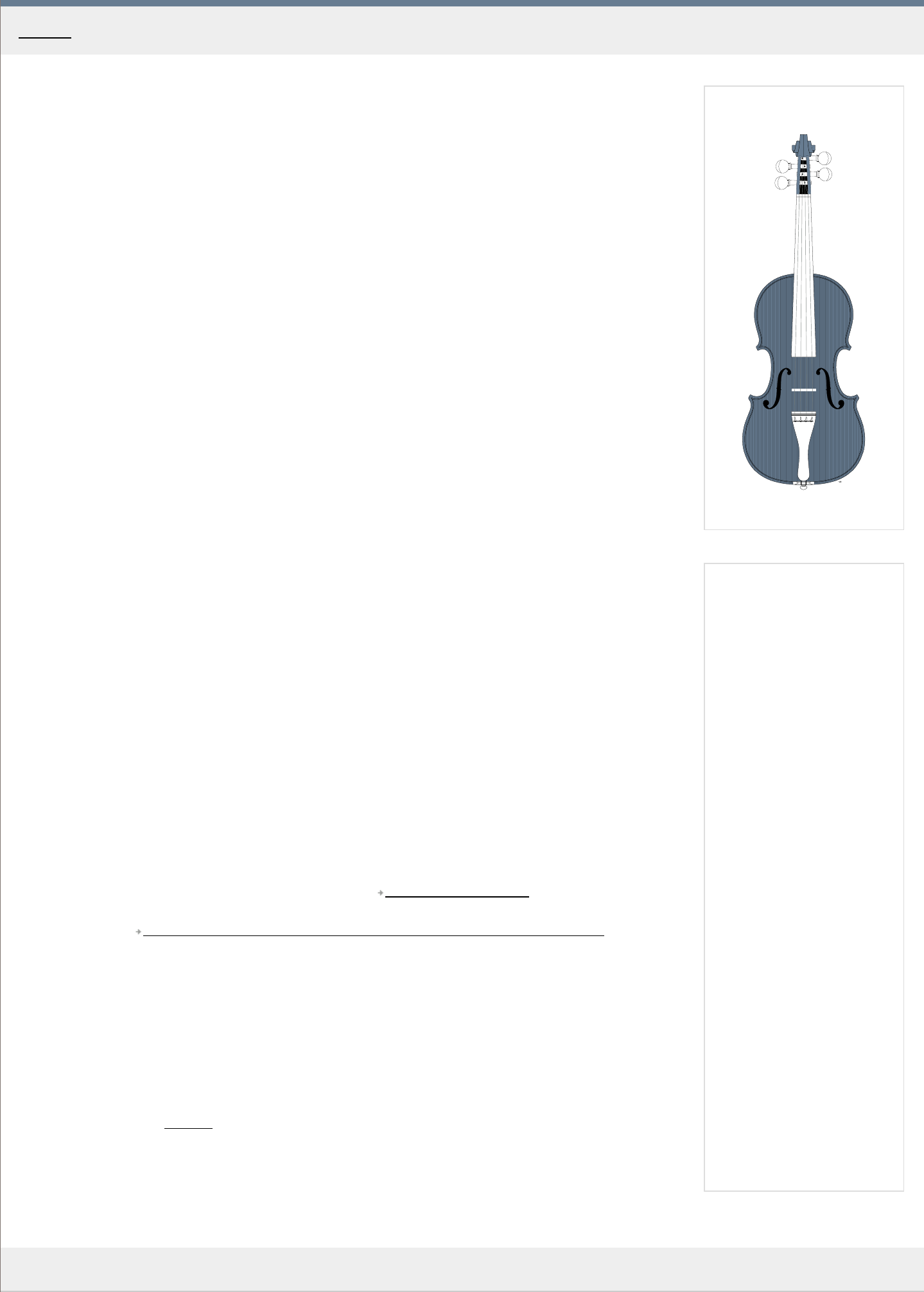
Stradivari Messiah 1716
MakingTheViolin.com
Welcome!
The purpose of this guide is to give basic information about violin making. The aspiring violin maker will
have the opportunity to build an instrument from start to finish with the help of step by step tutorials
accompanied by drawn images.
To make the best of the electronic format, all the images are in vector graphic format SVG, drawn to
exact real world dimensions. At every step of you building experience you can print out the plans and
drawings and use them in direct comparison with what you have at hand. The SVG graphic format is
supported by most modern browsers and editable by the free Inkscape.
My goal was to create a site that would give starting points to those interested in violin making. The
work is by no means complete. There is always room for improvement and I encourage anyone who feel
they might be able to contribute to do so, either by commenting on the pages, or sending their
contributions to me at [email protected]. All additions will be duly credited.
Together, we can make this site a rich, structured information source on violin making.
Enjoy your stay,
Vojtech Blahout
PS: You can now download the whole site as a PDF, see the link "PDF" on the front page.
Frequently ask ed questions
Q> I have a question/I don't understand what you mean by XY . Where do I get an answer?
A> If your question or a comment is about a section of the manual, please feel free to post a comment
on the appr
opriate page or register in the forum and ask your question there. I will try to get back to
you as soon as possible. Or you can always contact me by email [email protected].
Q> I want to edit or add to the content on the website, where is the registration?
A> Due to massive spam attacks, I was forced to close down this option. Please send me an email and
I'll set up an account for you. Commenting, at the bottom of every page, is available without
r
egistration, at least for now.
Q> I want to use the images on this site in my own project, presentation...
A> By all means, use whatever you need, but please consider linking back here or using any other
suitable way to acknowledge the sour
ce. You can edit the images in Inkscape.
Q> I see no images on the right side of the text.
A> If you are having problems viewing the images, click
http://caniuse.com/svg to see whether your
browser is supported. With some browsers, ie. Internet Explorer 6-8 there is the option to install the
Adobe SVG plugin
http://www.adobe.com/devnet/svg/adobe-svg-viewer-download-area.html to
correctly render the images.
Q> I use Internet Explorer and some of the images have wrong aspect ratio.
A>
Please, if you can, use Chrome or Firefox to view the site. I haven't found a reliable method to
display the SVG images acr
oss all browsers. The SVG rendering will hopefully get in line with other
browsers in the next release of the browser. Clicking on the image will display the correct full size
version even in Internet Explorer.
Q> I'm not sure my printer is precise enough to print the plans.
A> Please click on this Test file
and print it out on your printer. Check that the ruler matches yours. If it
doesn't you need to find a way to scale the output, usually in the printer's settings, so that the printout
passes the comparison test.
Home - F oreword
MakingTheViolin.com
1
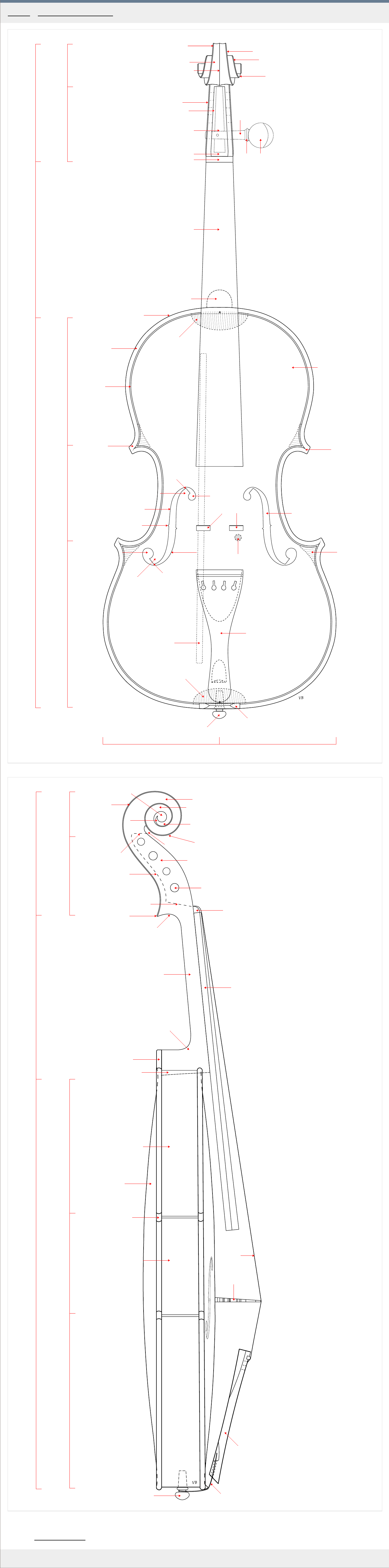
Chamfer
Fluting
Outterwall
I nnerwall
Pegboxfloor
Neckendwa ll
Nut
Centerridge
Firstturn
Secondturn
Finalturn
PegheadCollar
Shaft
Beesting
Corner
Fingerboard
Topblock
Endbutton
Upperwing
Notch
Lowerwing
Lowereye
Bassbar
Tip
Uppereye
Overhang
Purfling
Tip
Stem
Stem
Cornerblock
Bottomblock
Saddle
Topplate
Volute
Pegbox
Upper
bouts
Body
Cbouts
Lower
bouts
Neck
Scroll
Soundpost
Bridgeposition
Fhole
Button
Tailpiece
Shoulder
Bassside Treble side
2
Peghole
Nut
Pegboxwall
Ducktail
Nape
Thr oat
Chin
Fingerboard
Neck
Heel
Button
Backplate
Corner
Ribs
Pegboxf loor
Neckendwall
Voluteendwall
Eye
Firstturn
Secondturn
Finalturn
Comma
Chamfer
Volute
Pegbox
Upper
bouts
Body
Cbouts
Lower
bouts
Neck
Scroll
Endbutton
Cribs
Tailpiece
Tailgut
Bridge
Strings
Neckroot
Category: Tools and materials
Home - Tools and materials - Terminology

1
a
b
c
d
2
a
b
3
a
b
4
a
MakingTheViolin.com
When sharpening any instrument, there are two important aspects. You want the edge to be
as keen as possible and you also want it to be the ideal shape.
The sharpening of any tool takes generally two steps: Shaping and/or nick removal and
Honing.
Terminology
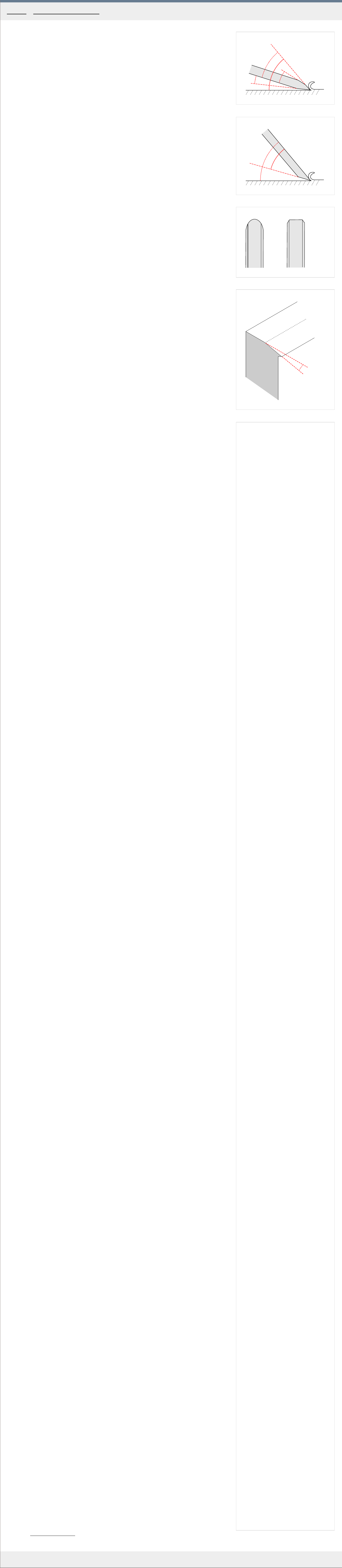
See Fig. 1 for the basic bevel up tool geometry. Bevel up tools include chisels, gouges and
block planes. "a" - Primary bevel angle, "b" - Cutting angle, "c" - Secondary bevel /micro
bevel/, "d" - Back bevel.
See Fig. 2 for the basic bevel down tool geometry. Bevel down tools include smoothing and
jointer planes. "a" - Bevel angle, "b" - Cutting angle.
1. Initial shaping or nick removal
In this step you decide the angle of the bevel. You also remove any nicks and irregularities
making the shape of the tip perfect.
Shaping equipment you need
If you want the bare bones setup, get a bench dual water stone 1000/4000. It should
measure at least 20 x 6 cm. Or even cheaper is a 600 grit sandpaper mounted on a block of
wood.
If you want to go electric, for large mass removals, wet grinders are the best. There is no
need to fear for overheating, but they are rather slow. Sides of the wheel can be used for flat
surfaces. Cheap ones use vitrified stones which are less efficient but degrade more slowly.
When you use your normal dry grinder, overheating is a great risk. When that happens, the
carbon in the steel combines with oxygen leaving you with just soft iron, plus you anneal the
tip making it soft. The whole length where this occurs should always be removed. Also,
quenching tips in water during dry grinding leads to tearing. The tip should be in contact with
the coolant at all times, so don't use dry grinders unless you really know what you're doing.
If you must use a cheap dry grinder, at least change the wheel for something like Norton
38A80 and buy a separate tool rest. If glazing occurs, which can happen when you grind
brass or with cheap grinders a diamond wheel dresser should be used to restore the wheel. It
can also be used to remove any humps on the wheel.
Belt sanders can on many occasions be used instead of bench grinders.
Shaping
The shape and the bevel depend on the metal used but also on the use of the instrument.
Japanese instruments are usually harder 62RC allowing for a keener edge, so a bevel of
higher 45° angle is needed to prevent breaking. With western blades which are a bit softer,
and less prone to chipping, the bevel angle can be less, say 25°.
Cutting the denser sorts of wood requires blunter bevel angles, whereas softer woods allow
for more sharply beveled tips. Ideally, the sharpest bevel should be employed which makes
the tip still strong enough to withstand the pressure of the wood.
2. Honing
During honing you make the bevels smooth as a mirror. Then you create the micro bevel,
making the tip as sharp as possible.
Honing equipment you need
The cheapest tools would be strops, leather or even better wooden. Cut a groove in a
softwood, maybe basswood, apply chromium oxide compound and you have a perfectly
shaped strop for honing. The same for the inner side. In seconds, you can make a wooden
strop that fits perfectly the shape of your gouge.
For chisels and plane irons, if you can, buy a honing guide. It will help you make the bevels
accurate and lead to consistent micro bevels.
An electrified alternative is the use of shaped felt wheels, which are ideal for honing the
inside of gouges. They are a great substitute for the fine bench stones. The to of the wheel
should rotate away from you. Belt sanders are great for honing with leather belts.
Micro bevels
Micro bevels save time, tools and energy. The finest possible edge in the shortest time. If you
need fine angular control, use a honing guide. Only takes half a dozen strokes.
Sharpening tools specifics
Chisels
1
. If new, remove the lacquer.
2. Lap the face so that the edge is not jagged. Make sure the stone is flat.
3. Fix the nicked chisels on your bench stone or wet grinder.
4. Hone.
A chisel should always be at the lowest bevel angle consistent with edge retention. Bevel
angle should be higher for nar
rower chisels, say 30°, to prevent chipping.
Japanese chisels are usually made of hard steel face combined with an iron back which add
toughness and flexibility to the chisel. The chisels are usually very hard 62-RC and therefore
quite brittle. They are usually sharpened at higher bevel angles. Ideal for softwoods. Most of
them are hollow on their face with just a couple of mm of a platform adjacent to the tip, to
ease sharpening.
Planes
With a new plane you will probably need to lap the sole. It is usually hollow. You don't need to
flatten the whole sole, but at the beginning, right before the mouth and at the end the sole
must touch. Use 90 grit on a sheet of glass, iron plate or stone.
True the bed. Put some paint on the iron, insert in position, remove and see there it imprints.
Carbon paper.
Dress the lever cap so that it is in perfect contact with the chip-breaker.
True the chip-breaker. At an angle that makes the point of contact at the very end. Have it set
as close to the keen edge as possible, maybe 1mm, because the closer it is the smaller will
the broken particles be resulting in smoother surface.
Sharpening the iron:
1
. If new, remove the lacquer.
2. Lap the face so that the edge is not jagged. Make sure the stone is flat.
3. Fix the nicked chisels on your bench stone or wet grinder.
4. Bevel down bench planes Stanley no 7, have the usual grind angle of 30-35.
Block planes such as the Stanley low angle 60 1/2 plane can be ground to 20° bevel and
5° back bevel to r
einforce the tip. Make sure the iron sits in the bed perfectly.
5. Hone.
Knives
F
or your knives a bench water stone, double 1000/4000 is alright. The bevels can range
between 10°-30° depending on the steel and application. If you are concerned about the
consistency of your bevels, you can use a spine clamp from you local stationery store. Put
the clamp on the back of your knife to serve as an angular guide.
Honing can be done the cheapest on a leather strap glued do a wooden block, dressed with
chromium oxide.
Gouges
1
. Bevel angle of 15 for soft woods and 25° for hard woods, 30°-35° with a mallet. All around
25°. In or
der to achieve the lowest bevel angle possible and the lowest gouge angle for
the easiest cut, make the outside bevel 15° and the inside 10°. The inside bevel reinforces
the tip and at the same time lowers the gouge angle required for a cut to 15°. This low
attack angle requires less pressure on the gouge and makes your cuts more precise.
2
. You may also decide to change the shape of the tip's end. Square end is good for most
purposes, finger
nail end may be better for the scroll.
3. To hone the gouges, either use a leather belt charged with chromium oxide on an electric
belt sander
. If you prefer manual, go with the wooden strop charged with chromium oxide.
For the inside flute, a shaped felt wheel charged with chromium oxide is good. again going
manual, cut the edge of a scrap wood which reflects the shape of the inside of the gouge
perfectly. Dress with chromium oxide.
Scrapers
A well sharpened scraper should make clean shavings, not dust. In hardness RCs of up to 52
are now available. To create the edge, you need to burnish the scraper. Use a round burnisher
or >RC60. Don't use the backs of you chisels, they most likely are not hard enough. Don't use
screwdrivers as the chromium/nickel coating is thin.
1
. Joint the scraper first to give it a smooth edge at 90° to the sides. A jointing jig can be
used with squar
e scrapers.
2. You can stone the surface, at the side of the bench stone. 1000x
3. Put some nose grease on the burnisher.
4. Clamp the scraper in the vice, and make a couple of strokes parallel to the scrapers edge
with the bur
nisher slightly tilted as in fig. Hold it by the handle with one hand and by the
tip with the other. Move the burnisher in a little to avoid using just one spot on it. In softer
scrapers this will result in a small hook on both sides. With greater angles the scraper will
have to be tilted more to the ground to bite. Use as few passes as possible. Try the
scraper on the wood you intend to use it for.
5
. If you need more hook, run the burnisher at a slight 2°-10° angle to the edge. Do that a
couple of times. Check again.
T
o "pick up" the hook after it has become dull, reburnish again with a few strokes. If that
doesn't help any more remove the hook with the jointing jig, stone and burnish again.
Scraper plane
The scraper plane can be used when thicknessing the ribs. A 45° bevel is usually used. On
top of that, you can create a hook at the end with your burnisher angled at 15°.
Stone truing
After a while every stone will loose its flatness. This may not be a big deal with gouges, but
when sharpening chisels or plane irons, the stone must be reasonably flat. To true your stone,
you can sue a coarse diamond bench stone, silicon/carbide paper on glass or even coarser
stones, which can true your finer one.
Wood cutting tips
When parallel grain cutting, always cut with the grain, that is when the grain is rising up
away from you.
If cutting end grain, always consider the skew cut. It is less demanding of the edge and
lowers the bevel angle further.
When planing keep the mouth just wide enough for the shaving. This also results in smaller
particles, smoother surface. Take thin shavings, they also allow for tighter mouth. Skew the
plane wherever applicable. This applies especially if you have to cut against the grain.
Use a low angle plane, when cutting end grain.
For the cleanest cut with gouges, roll-cut.
Category: Tools and materials
Home - Tools and materials - Sharpening
1
2
20C
40C
60C
80C
100C
3
MakingTheViolin.com
Hide glue and gluing
In the construction of violins only high quality hide glue should be used. Other glues, such as
the white, yellow glue the cabinetmakers use, should be avoided. The main reasons for hide
glue are reversibility /the joint can be taken apart and re-glued again/ and specific toughness
of the joint with no creep and good acoustical properties.
What you need
1
. Some hide glue. It can be in the form of small flakes, pearls or powder. Usually offered are
str
engths varying from 250 to 400 grams. Stronger sorts give you less working times so
take the middle road and buy something of around 300 grams of strength. Usually small
amounts of glue are used during building so you don't have to buy more than 100gr of dry
glue to get you started.
Avoid the hide glue that is offered liquid and premixed.
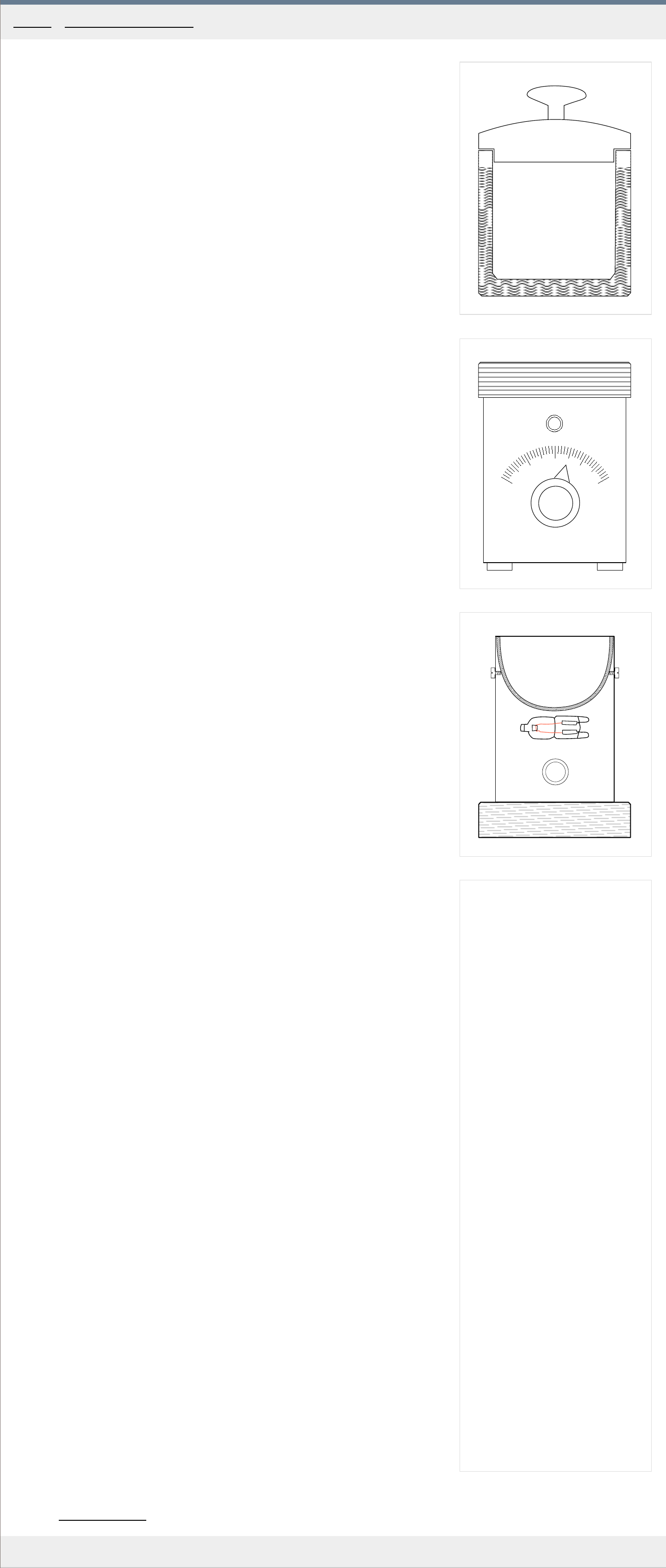
2. A glue pot/kettle. It should be rather small, ideally 8-10 cm in diameter, allowing you to
pr
epare small amounts of glue quickly. Hide glue temperature must never exceed 70C, so
you should be able to regulate the pot's temperature or its power output should be in the
range of 10ths of watts. A regulated, double bottom pot with an insulating water-bed is
perfect. See Fig. 1 and Fig. 2 for an example of the pot and hot plate.
If you are pressed for money, or love to DIY, you can build a small glue pot yourself. It will
work even without the water
-bed, but you must make sure the wattage of the heating
element is not more than 60 watts - a small halogen light bulb, such as the G9, can serve
well here. The upside is that the heat up times are short and you will have a batch of hot
glue ready in a minute. The downside: You will have to watch the pot like a hawk, keep
stirring and turn it off before it overheats. It may seem complicated but when you get
used to this, you can prepare small amounts of glue very quickly. See Fig. 3 for an
e
xample of such a setup.
This glue pot is made of a round wooden base and a sheet of metal turned around a bell,
which serves as a pot. The heating element is the halogen light bulb mentioned above.
Use your imagination.
The bottom line: You don't need anything fancy or regulated but a good thermometer
befor
e you get the feel for this is a must.
3. A set of brushes and knives. One smaller 5 mm wide all-purpose brush, one larger 20 mm
wide for bigger jobs. A palette knife will be used to work the glue into the seams when
gluing to top and bottom plates to the ribs.
Preparing the glue
1
. For a start, put a teaspoon of hide glue in the glue pot and add about 100ml of fresh
water
.
2. Stir and let stand for 1-2 hours. When you see the glue has gelled and grown in size
considerably, it is time to heat it up.
3. Turn on the glue pot and make sure the temperature never exceeds 70C for longer periods
of time. Should your hide glue start to boil, don't use it, and prepar
e another batch.
4. Keep stiring until you are sure there are no undissolved pieces in the pot.
5. Check for the thickness of the glue. Visually, the glue is hot and thick enough if a film
starts to for
m over its surface. You will learn to guess the right thickness by letting the
glue drop from the brush. The medium thickness hide glue should feel oily between your
fingers. The thin hide glue used for glue sizing should almost be the consistency of milk.
Make sure the glue is about 70C when testing for thickness.
Application
1
. Always try to work in a warm room with no droughts so that you have more time to make
the joint.
2. Preheat the critical joints with a hair dryer, ie. center seam joints.
3. Make sure everything fits right without the glue first.
4. Have everything to hand, you need to act quickly and precisely.
5. Don't use more glue than necessary and always remove the surplus with a damp brush or
towel. Sometimes it may be better to wait for the glue to gel a bit for easier removal. Be
especially car
eful with the areas that will be varnished. Areas with hide glue blotches will
not absorb the stain properly, leaving marks.
6. When you are using the palette knife, always have it preheated in hot water, otherwise
the glue gels fast when in contact with the cold knife.
Drying times
Under nor
mal humidity and temperature the hide glue should be left to dry for about 12-24
hours. Usually overnight should be enough time. More structurally important joints, such as
the center joint or the neck joint, should be left undisturbed for the full 24 hours.
Hide glue shelf life
The dry hide glue should be stored somewhere... dry. Properly stored, it has an almost infinite
shelf life.
The shelf life of the prepared hide glue depends on many factors: humidity, room
temperature, possible contamination, thickness. It all boils down to how bacteria friendly
your workshop is. The freshly prepared glue is the strongest, so for critical joints, ie. when
joining the billets for the top and bottom plates, I would always use fresh glue. On the other
hand, many violin makers may leave their glue in the pot for days without apparent loss of
strength.
Some people prepare the glue, let it cool down, cut it up into small cubes and put them in a
fridge.
The signs of bacterial degradation are the change in color, often turning brown, tiny watery
pits on the surface and a bad smell.
So if you want to stay on the safe side, always prepare a fresh batch of your glue.
Category: Tools and materials
Home - Tools and materials - Glues
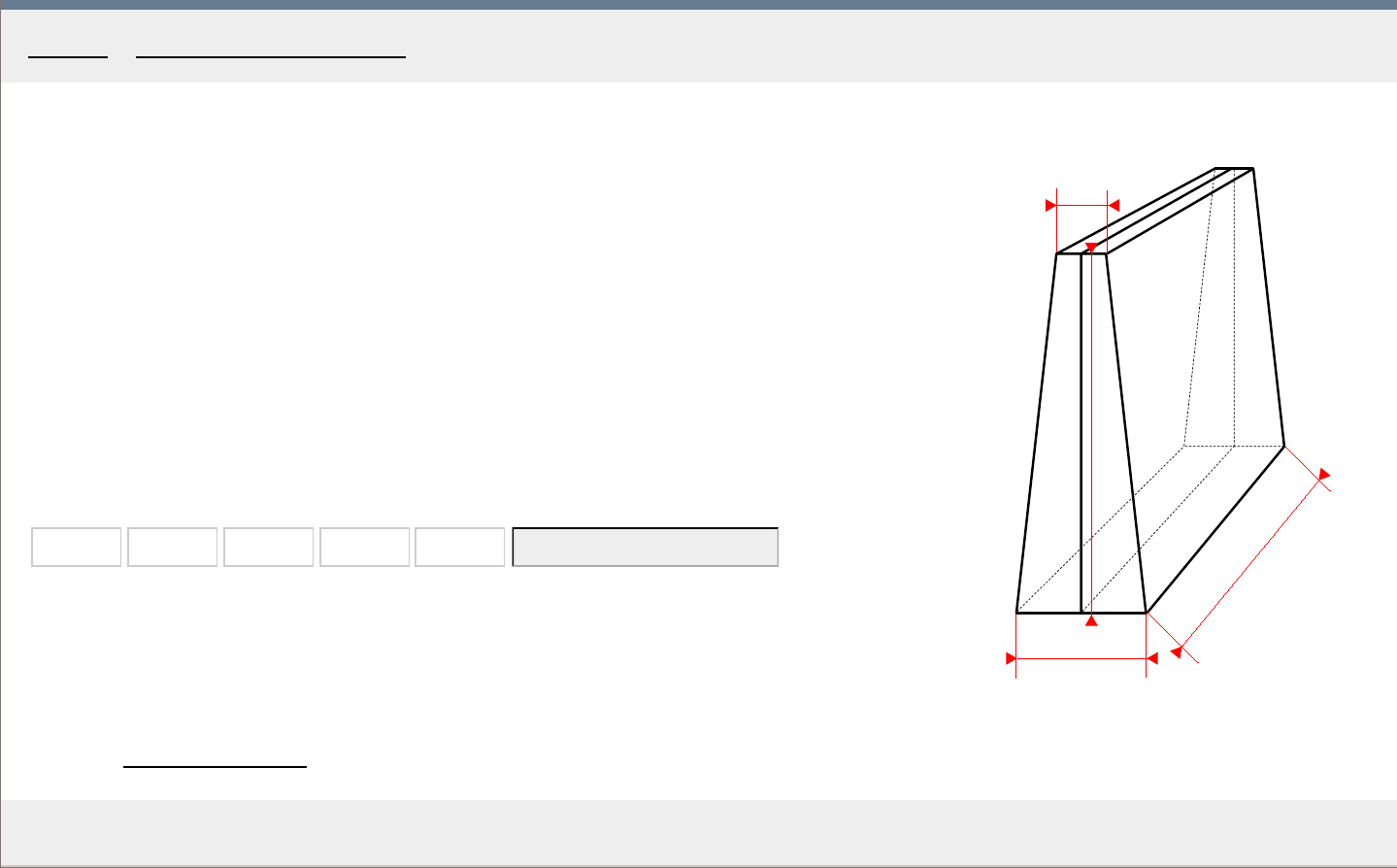
A method of ascertaining the specific gravity of wood is to submerge the wooden billet in water
and divide the length of the submerged part by the total length of the billet.
Alternatively, you can use the widget below to calculate the specific gravity for you. Be sure to
measure the dimensions and weight as precisely as possible. Typical results range from 0.38 - 0.45
for spruce and 0.50 - 0.60 for maple.
The dimensions are input in millimeters , the weight in grams . The widget first calculates the
surface = ((a+c)/2)*b, then the volume = ((surface +surface )/2)*d and finally specific gravity
= weight /volume .
a b c d Weight
Calculatespecificgravity
a
b
c
d
MakingTheViolin.com
Determining the specific gravity of wood
Category: Tools and materials
Home - Tools and materials - Specific gravity calculator
1
2
B
C
A
3
X1
X2
4
MakingTheViolin.com
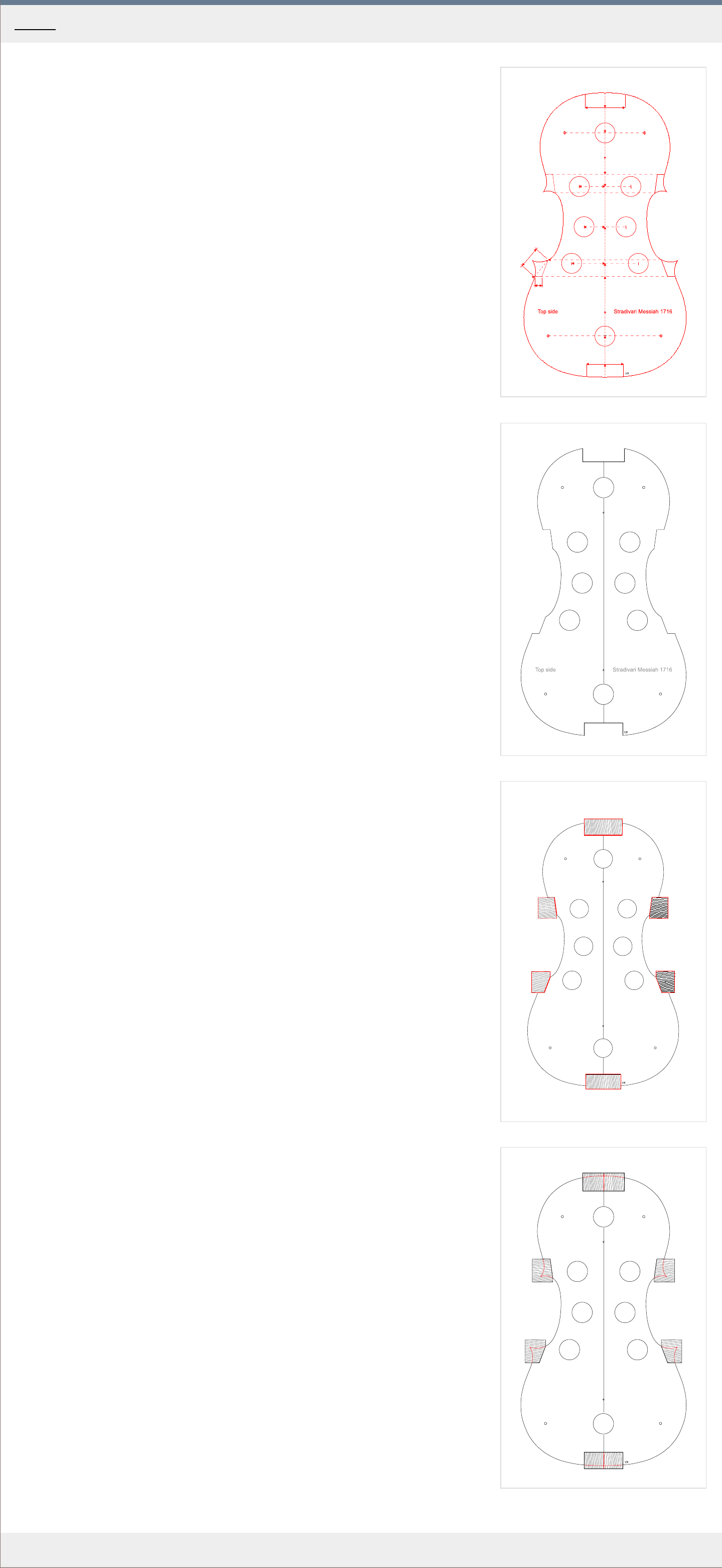
A few thoughts
The template is the basis of all your work on the violin, so a lot of effort should go into its
proper execution. You have to decide whether you are building an exact copy of an existing
instrument or an approximated interpretation of an existing instrument or an original
construction.
In case of an exact copy, you will use a full size template describing the outline of the copied
instrument to the greatest detail. If this instrument is of any considerable age and has been
used, it will have at least some wear. That wear will get copied as well. The shape of the
instrument itself changes over time, the wood shrinks differently in various directions. All that
gets copied. Choosing this approach, if you want to arrive at something "right" you have to
work very precisely, because you are at least 8 "generations" away from the original outline
and every generation brings some amount of error with it.
In case of an interpretation, you can still use a full size template, which you will "correct" to
some degree. You can remove obvious spots on the outline, where the wear has caused the
shape to deteriorate and you can also correct some of the asymmetry.
Besides the full size template, you can use a half template, which you flip on the other side to
get perfect symmetry. The downside of this is that you will have to choose which half of the
original violin you will use. Without correction, if the original violin is very asymmetrical you
will end up with a very differently shaped violin. To illustrate this, get a picture of someone`s
face, and use just the left or right half to reconstruct the whole. The change may be quite
dramatic.
Knowing all that, for a novice, who is very likely to introduce a lot of errors, the symmetrical
template is almost always a better choice. Remember, errors tend to accumulate with
iterations.
You may also decide that you want to construct the outline yourself, without it being directly
based on any existing violin. There are many systems of violin construction out there but to
me the most simple ones, based on the use of compass and basic geometry seem the most
plausible. For an in depth approach to this, see the great François Denis` book Traité de
lutherie.
Because this manual is meant mainly for beginners, we will take the full outline and convert it
into a half template from which in the next chapter we will construct a perfectly symmetrical
mould. The full size outline is based on the famous Messiah violin, built by Antonio Stradivari
in 1716. This violin is in perfect shape with no discernible wear, so we will even out just the
obvious irregularities which are the result of handwork.
The template
1
. For the half template use a 2 mm thick sheet of ple
xiglass, or aluminium which is at least
15 cm wide and 38 cm long.
2. Get the outline of the violin you want to interpret. You can either copy the outline from an
e
xisting violin or, you can buy a Strad poster, which, on its back has the outline plus the
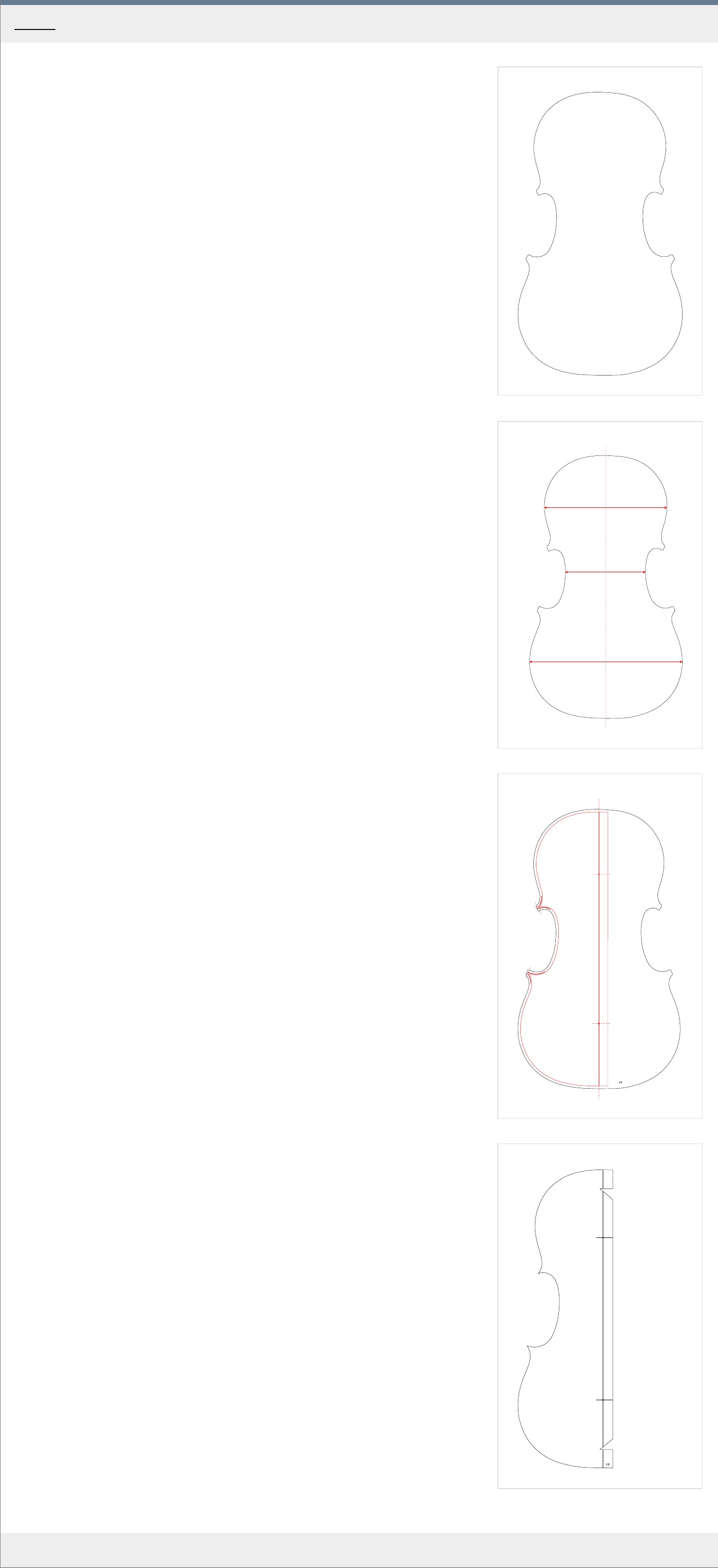
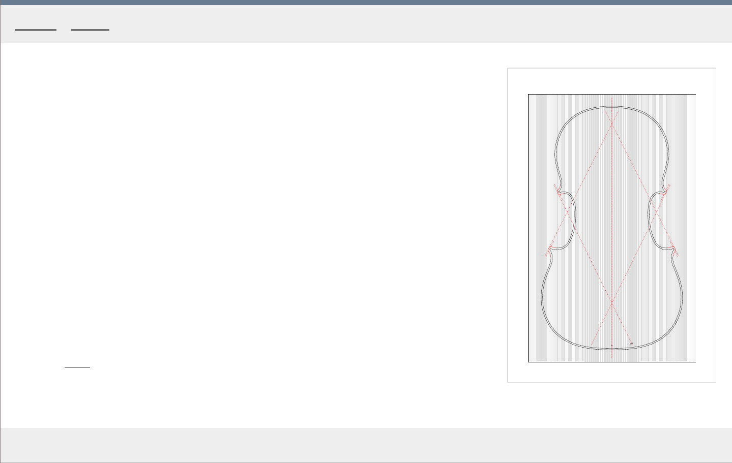
arching curves and other measurements. The outline should look something like in Fig. 1 .
If you decided to build the Messiah violin in this guide, you can take a short cut and print
out the finished half template in Fig. 4 . This outline should be 350 mm long. If for any
r
eason you cannot print the outline to scale from your web browser, save the svg image
and print it from Inkscape (with proper margins). Now you can skip to the gluing as
described in paragraph 9.
3. Copy this outline using a photocopier or print out the outline in Fig. 1 . Y
ou will need a
printer, that is capable of printing on A3 size papers as the outline is over 35 cm long
exceeding the A4 format.
4. Determine the centerline of the outline. Measure the widths in points A, B
and C, divide by
2 to determine the true center of the violin. See Fig. 2 .
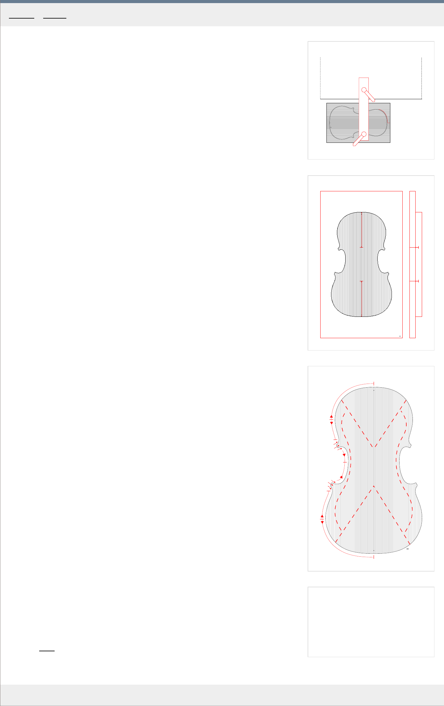
5. Mark out the points X1 and X2 , about 8 cm in fr
om top and bottom, see Fig. 3 . These will
serve as fixing points for correct alignment later on the mould.
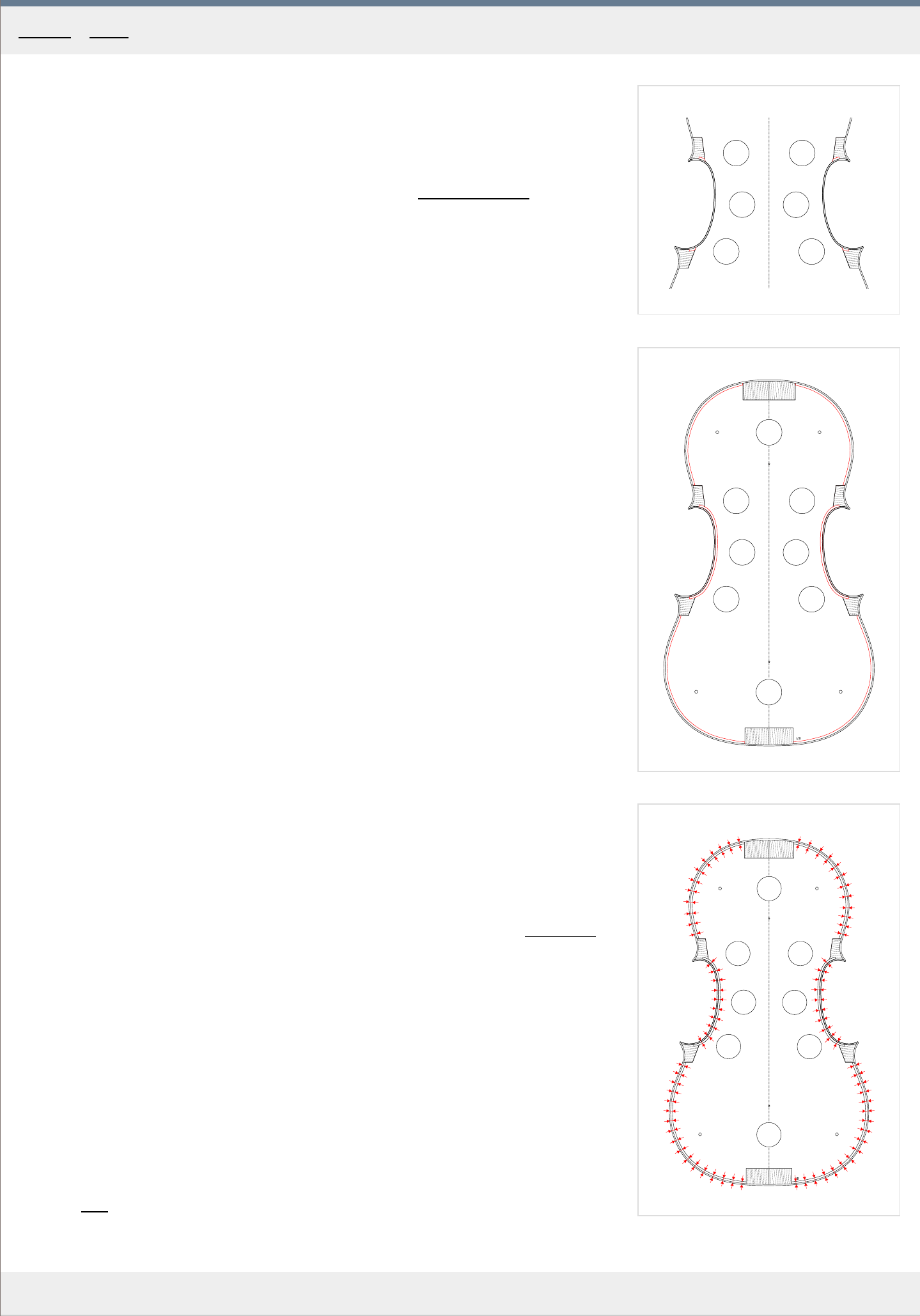
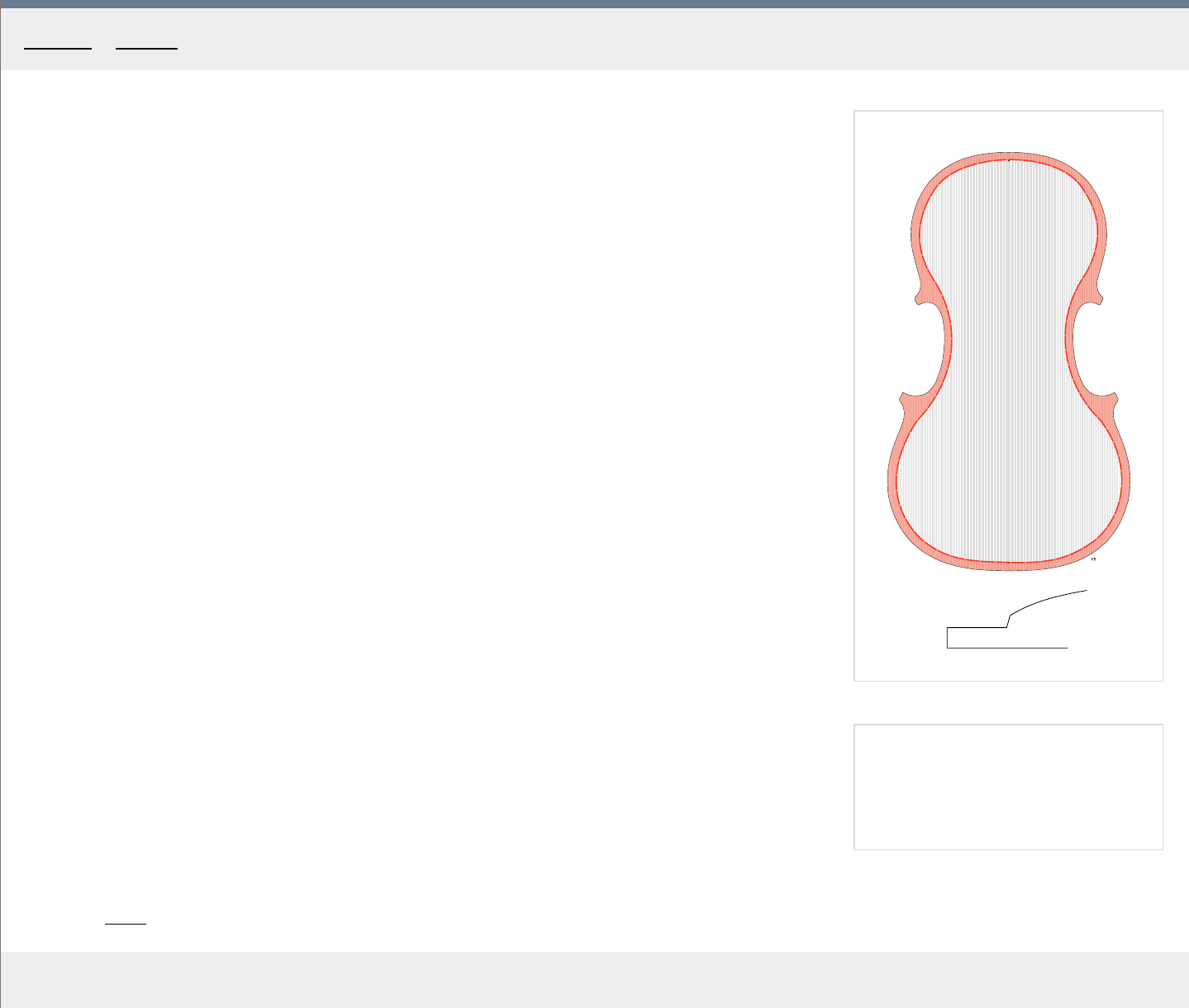
6. On the side, which you chose for the half template, construct the contour of the template.
This contour is infer
red from the plate outline, minus the overhang, minus the thickness of
the ribs, which in our case makes, in total, about 3.3 mm. Use a compass to draw a
parallel line inside the outline, see the red line in Fig. 3 .
During this process of parallel tracing you also have a chance to correct anything you
don`t lik
e about the original outline of the violin. You want to even out the bumps without
loosing the original.
7. The general 3.3 mm inset can be applied to all of the shape, e
xcept for the corners. There
the inset gradually increases. The increase is steeper in the C bout and less so coming
from the upper and lower bouts. Depending on the original model, the end of the ribs may
be 0-4 mm inset from the end of the corners. The good common value here is 2 mm, see
the dashed lines denoting the ends of the ribs in Fig. 3.
It is therefore a good idea to try to draw the complete corners, including ribs, for
reference. From this you can infer the inner outline of the mould. Study the corner
construction in Fig.3 .
8
. Once you have the template outline complete, draw the remaining line which runs parallel
to the centerline about 8 mm off the centerline, closing the template.
9. Glue the half template outline to the plastic or aluminium sheet as mentioned in P
ar. 1. It
is preferable to use some sort of superglue, as other glues may tend to peel. This, of
course, depends on the material you`re using. Avoid the use of water based glues
altogether as those will cause the paper to spread, leaving you with a bigger outline.
10. Carefully cut out the outline of the template and finalize its contour with a file. About 3 cm
fr
om top and bottom cut out notches which will help you see the centerline when aligning
the template to the mould.
You can see the finished template in Fig. 4 .
Home - Templates
1
184
115
100
50
18
46
50
32
26
41
9
26
a
b
x1
x2
c2
c4
c5
c3
c6
c1
c7
c8
e1 e2
e4e3
2
3
A
B
C D
FE
4
MakingTheViolin.com
The outline and measurements
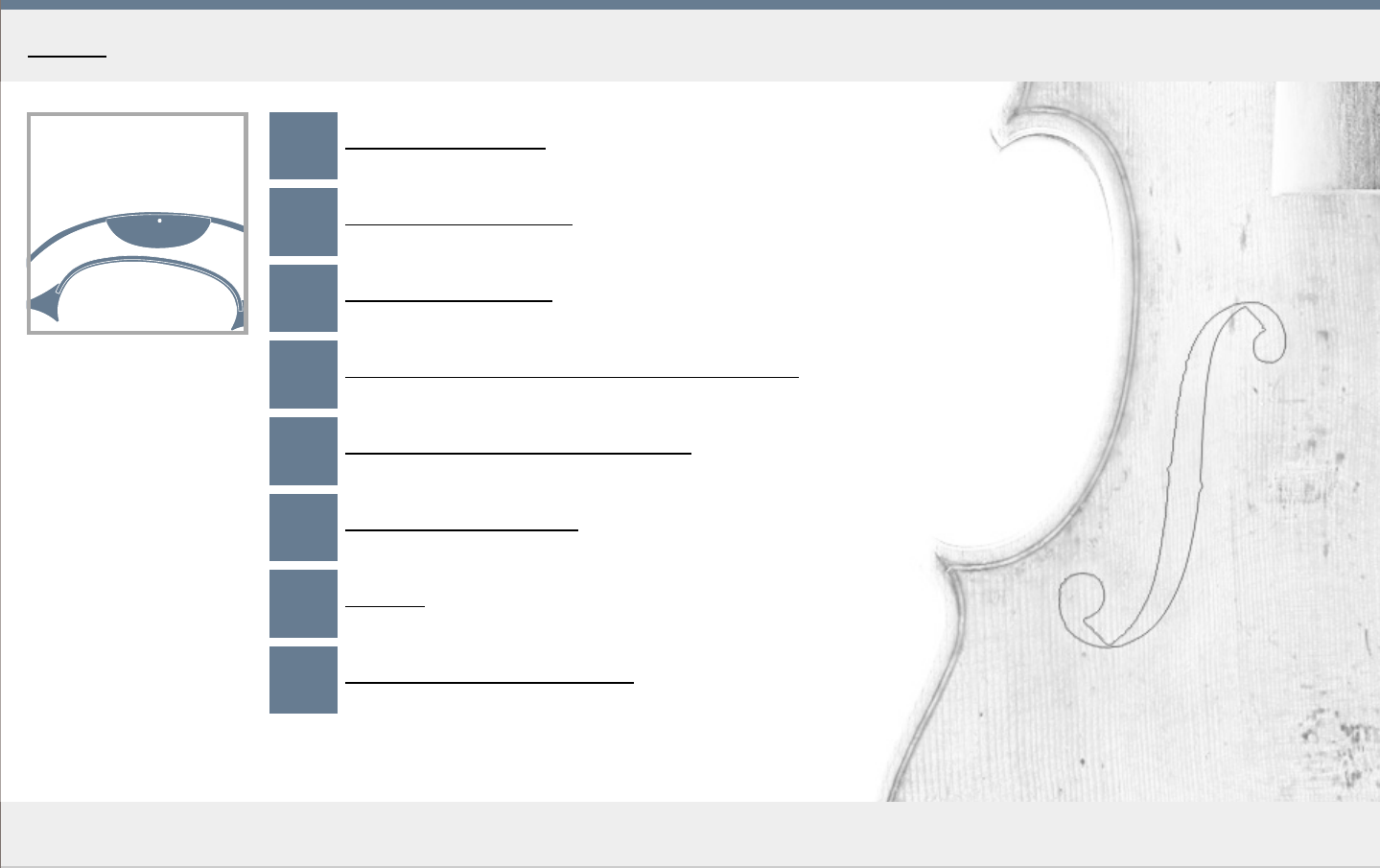
1
. For the mould, use a 12 mm thick, 400 mm tall and 250 mm wide piece of wood. It is
important that the wood is as stable as possible, so multi-layered plywood or battenboar
d
are preferred.
2. After you have cut it to the right dimensions, you need to transfer the outline.
3. First, draw a centerline on the wood, then align the template with it.
4. Now you need to drill two holes, about 8 cm in fr
om top and bottom of the template, on
the centerline, drilling through the template itself as well as the wood. For this, a drill press
is the best. See the Templates chapter for the exact location of the points.
5. Then get two wooden pegs, matching the diameter of the drill bit. Or you can use the drill
bits themselves.
6. Securing the template in perfect alignment with the centerline in this way, scribe a line
along its contour, flip the template on the other side and r
epeat. Repeat also on the other
side of the mould, making sure the orientation of the template is correct.
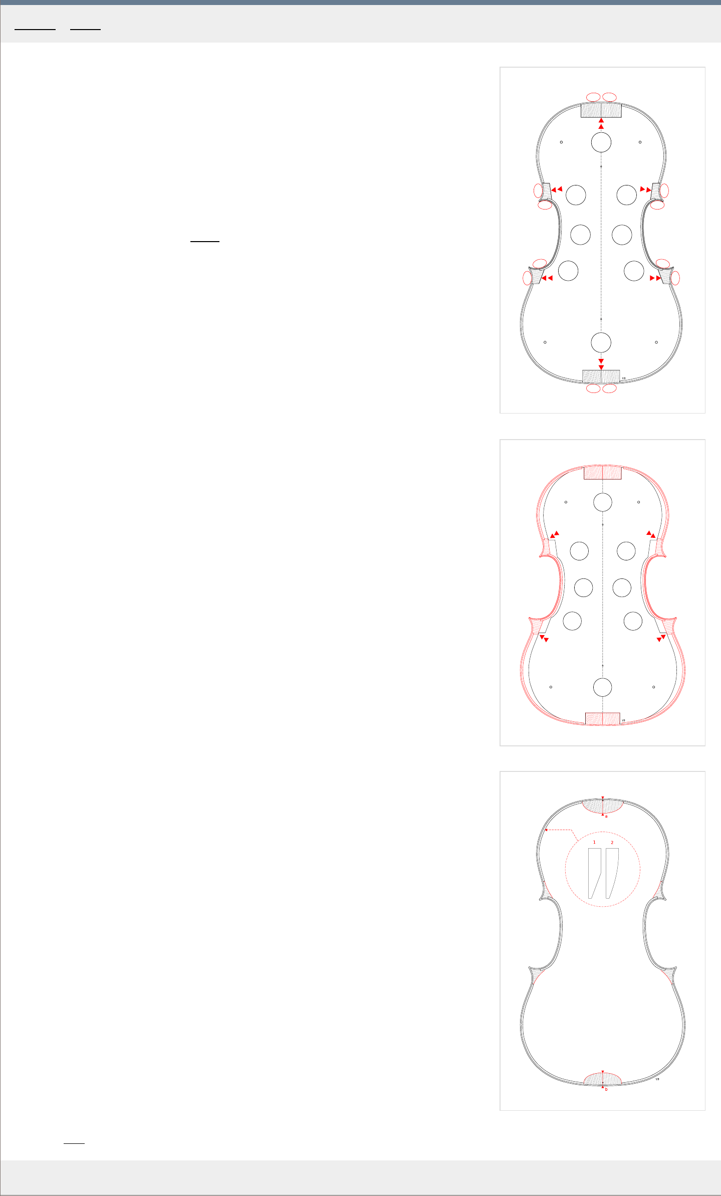
7. Now you need to transfer the lines as in Fig.1 , all measur
ements are in millimeters. The
cornerblock recesses are drawn as follows: 1. Draw the "a" line, 2. Using a compass, from
point x1, measure 26 mm and create the point x2 on the C bout, 3. from x2, draw the "b"
line connecting it back to the "a" line.
8. Repeat on all remaining corners. Repeat for the other side as well.
9. It is also a good idea to mark the top and bottom side of the mould so that you always
know which side is facing you. Also, add an inscription on the top of the mould about the
name and author of the sour
ce violin you are interpreting.
Cutting out the mould
1
. After you have marked out those lines, you can proceed to cut out the actual mould. The
best tool for this is the band saw, which will mak
e it easy for you to achieve the perfectly
perpendicular cuts. If you are cutting the mould by hand, make sure you stay well off the
line and that you are not undercutting into the line on the bottom side.
2. Use a file to finish the contour.
3. For the clamp openings "c1-c8", a press drill again is the best tool. Predrill all the holes
with a 3 mm bit. Then, using a 25 mm drill bit, to avoid splitting, start a hole on the top,
drilling about 1/3 in, then flip the mould and finish.
4. The four "e1-e4" holes should now be predrilled with a 2 mm bit. F
our screws will be later
used here to elevate the mould above the workbench surface a bit when attaching the
blocks.
You can see the finished mould in Fig.2 .
5. Dry soap should now be applied on the perpendicular side walls of the mould, ex
cepting
the areas the blocks will be glued to. This prevents accidental gluing of the ribs to the
mould, should you spill some glue where it does not belong.
6. The areas where the blocks should stick - the longer sides of the recesses - should be glue
sized with thin hide glue.
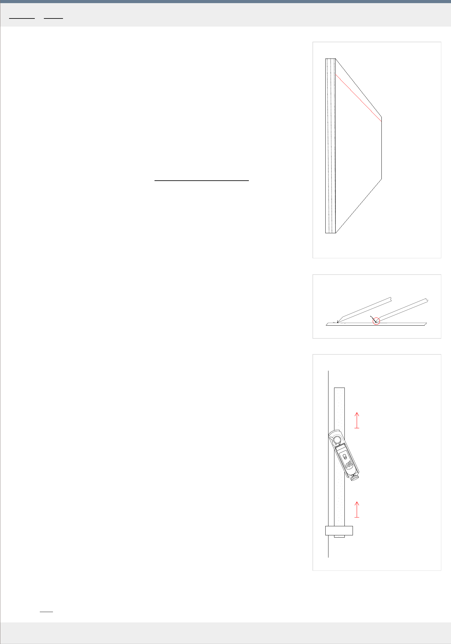
The blocks
1. Cut spruce blocks to the following sizes: Top "A": 32 x 50 x 22 mm , Bottom "B": 34 x 46
x 20 mm , Upper cor
ners "C, D": 33 x 25 x 28 mm , Lower corners "E, F": 33 x 25 x 28
mm . The grain should run perpendicular to the bottom plane on which they "sit", allowing
for easy, precise cutting {from top to bottom} later on.
2. At the bottom side of the mould, screw in four screws into the predrilled holes so that the
mould gets lif
ted evenly by approximately 9 mm . Make sure that all four screws make
contact with your flat workbench and that no rocking is present.
3. Fit the blocks in the mortices in the mould. The gluing surfaces are the thick red lines in
Fig.3 It is important that these surfaces ar
e in perfect contact with the mould. The top
and bottom "A, B" blocks should have a slight gap at the sides allowing them to be
inserted easily. Make sure the annual rings are directed away from the mould as in Fig.3 .
With most violins, the height of the ribs decreases gradually along the length of the body.
Ther
efore, in the finished violin, the bottom block may be 32 mm tall, whereas the top
block may be 30 mm in height. This, of course, affects the upper and lower cornerblocks
as well. For Messiah, the final heights in the finished rib structure is as follows: A 30 mm ,
B 32 mm , C 30.5 mm , D 30.5 mm , E 31.5mm , F 31.5 mm .
4
. With these numbers in mind, if necessary, trim the blocks to their final heights leaving
them about 2 mm taller
.
5. Glue the blocks to the mould using medium thickness hide glue. Apply the glue to the
longer side of each mortice only
. Remember, you will have to break the blocks off the
mould when the ribs are finished, so avoid applying too much glue. Hold in position with
your hands for about 30 seconds. Let dry overnight.
6. Once the glue is completely dry, sand the blocks down on both sides, bringing their height
to about 1 mm above the final numbers. F
or this, use a long belt of sanding paper
clamped down on both ends to your workbench or glued onto a flat /ie. 6-8 mm thick glass/
plate. Later on you will finalize the heights of the ribs using this method again, but this
time with the ribs already glued on.
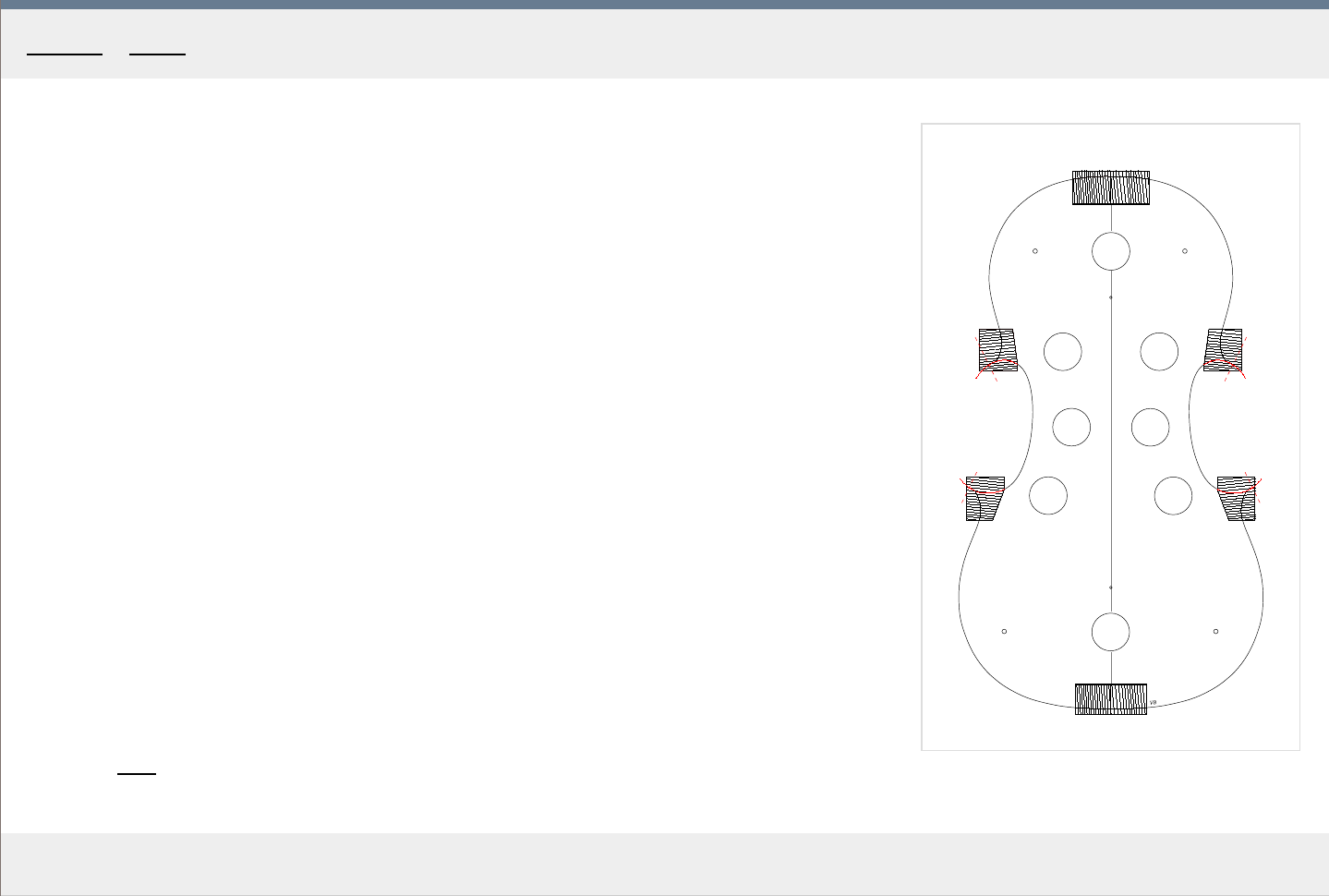
7
. Take the template, realign it with the mould, mark the contour on all the blocks with a
pencil or a scribe. Mark the true center of the violin on the top and bottom blocks. See the
r
ed lines in Fig. 4 .
8. Flip the mould over and repeat the marking on the other side.
Home - Mould
1
a
b
x
2
a b
3
MakingTheViolin.com
Preparing the ribs
1
. Choose good maple, which will satisfy you both visually and physically.
The wood should probably be flamed and flexible and the flame should match that of your
back. R
emember though, that more flame means the maple will be more difficult to work
with because its structure is more complicated with some parts denser than others. This
may prove problematic especially if you have no previous experience in wood bending. So
if this is your first violin, use plainer, less figured wood.
Look at the cross section in Fig. 1 . The gr
owth rings should run as parallel to the sides of
the ribs as possible, to ensure greatest stability. Also, the height "b" should be sufficient
for the violin you are building, plus about 4 mm . (36 mm for the Messiah)
2. Decide whether you are going to make the ribs for the upper and lower bouts in one or two
pieces and cut the ribstock accor
dingly. See Gluing the top and bottom ribs
if you don't
know how long the upper and lower bout should be.
3. Fix a jack plane upside down in your vice, carefully hold the ribstock in your hands, and
plane the "a" side of each of the ribs so that its level and straight. Alternatively, you can
use a shooting boar
d for this.
4. Draw the maximum height "x" line parallel to the "a" side you have just planed. This line
denotes the maximum height of the ribs, usually in the back of the violin, ie. 32 mm +
add 4 mm as safety mar
gin.
5. Cut through the line using a knife and a steel ruler, or use the mounted plane again to
r
emove material to the line.
Thicknessing
1. Now that you have all the ribs trued and cut to the correct height you need to adjust their
thickness to appr
oximately 1.5 mm .
It is best to use a rectangle scraper to remove most of the thickness. To make the surface
even it is advised to use a block plane with a blade r
eground for scraping as in Fig.2 .
Blade "a" is the normal block plane blade, which doesn't work well with the dense, flamed
ribstock. On the other hand the "b" blade, which when reground works as a scraper, is
perfect for the job.
You can, of course, instead of the scraping plane, use your regular scraper, but in that case
you will need to k
eep a keener eye on the evenness of the thicknessing and the whole
process may prove more cumbersome. It all depends on the initial thickness of the
ribstock.
The thickness and its even distribution may be checked with a thicknessing caliper or more
efficiently, the tar
get thickness can be punched into the ribstock using a graduation
punch. Set the punch to the final thickness and make a network of holes covering the
whole ribstock. Working with the plane scraper, when all the holes are gone, you have
arrived at the correct thickness. See the dots in Fig. 3. for reference.
2. Clamp the rib down to your workbench and start scraping away from the clamp, as in
Fig.3 . T
o remove wood as evenly as possible, tilting the scraper a little may help, as the
flamed pattern consists of patches of softer and harder wood.
3. As mentioned previously, during this stage, also employ the scraper plane to remove any
unevenness.
4. After you have reduced the thickness to 1.5 mm , continue r
emoving material down to 1.2
mm . Again, make sure the thickness is evenly distributed along the whole length of the
rib.
Category
: Ribs
Home - Ribs - Preparing the ribs
1
a
b
c
d
MakingTheViolin.com
Cutting the C blocks
1
. First, take a sharp chisel and remove all the wood about 3 mm beyond the projected tips of
the cor
ners. See the red dashed lines in Fig.1 for the approximate position of the cuts.
2. Using a suitable gouge, start paring away the wood on the upper and lower corner blocks
wher
e the C ribs will be, see the contours in red, "a, b, c, d ", in Fig. 1 . As in the image,
naturally extend the curvature past the tip of the cornerblock.
Make sure the bottom of the block you are working on is resting securely on your
workbench and that the only pr
essure applied is to the block itself, otherwise the block
might snap off as it is only lightly glued.
Make frequent checks of the lines on the other side of the blocks to make sure you`re not
undercutting.
Also, with the help of a small square, keep checking everything is perfectly perpendicular.
3. Finish with sanding paper on a stick of suitable diameter, making sure that the point where
the blocks meets the mould mak
e a transition as smooth as possible. Run your finger over
it to check for smoothness.
4. Check the contour again by realigning the template with the mould.
Category
: Ribs
Home - Ribs - Cutting the C blocks
1
2
MakingTheViolin.com
Preparing the mould and the ribstock
1
. Screw the four screws in the mould again so that they rise the corner blocks about 1.5-2
mm above the surface of your workbench. P
ut the mould on your flat surface and put the
rib stock right next to the corner blocks checking that it overlaps by 2 mm at the bottom
and 2+ mm at the top.
Don`t forget that the height of the ribs is decreasing along the length of the violin body, so
with a 2 mm over
hang at the bottom block, you will get 4 mm at the top block.
2. Choose the ribstock pieces for the C ribs. Decide the orientation of the pieces with regar
d
to the slant of the flames. They usually slope down towards the player on both sides (the
flames on the neck later on should match that). Make sure their surface is perfect,
especially on the outside, correct with a scraper.
3. Prepare the clamping blocks used to hold the C ribs in place as in Fig. 2 . These can be
made of some har
der wood to the dimensions of 110 x 35 x 15 mm . Two pieces are
needed. For the exact angles, you can print out the Fig. 2.
Bending tips
The temperature of the bending iron should range between 200-250 Celsius . You can get a
thermostatically controlled bending iron, or you can learn to estimate the temperature by
moistening your finger in the water and touching the iron briefly. This takes experience.
Also, practice bending on scrap rib stock first. You need to learn how much pressure to apply,
how fast to proceed, how the heat in the iron is distributed and what is the best temperature
for the actual wood you are bending. Too little heat and too much pressure and you will break
the rib. This applies especially for highly flamed maple. Too much heat, on the other hand,
applied for too long will vaporize all the water and you will scorch the rib.
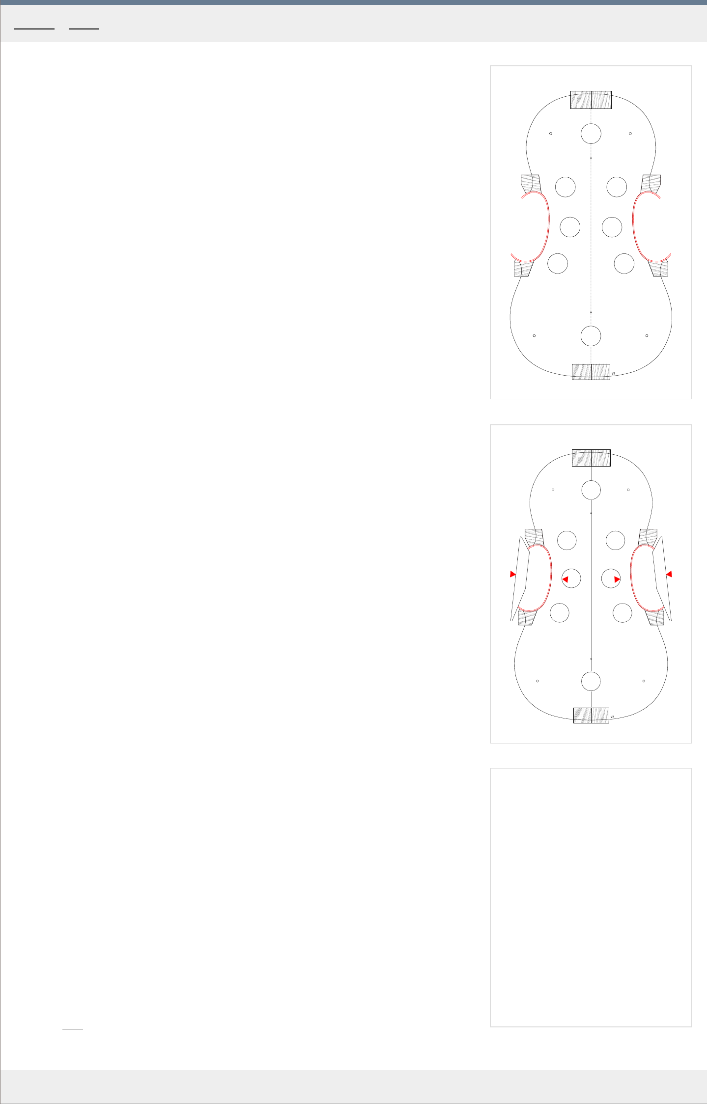
Bending
1
. Put a sufficiently long piece of rib stock in water and let soak for a few minutes.
2. Heat up the bending iron and bend the C ribs so that they fit the mould as closely as
possible. No e
xcessive force should be needed. You should be left with C ribs that have no
gaps along their inner side, like in Fig. 1 .
When driven home, looking from the side, they should be in contact with the workbench,
e
xtending beyond the elevated corner blocks by about *2 mm*, as mentioned above. Also,
using a small square, check that they are at right angles to the workbench.
Clean the bending iron after each bending with a damp cloth to reduce the staining of the
wood.
3. Shorten the ends of the ribs, if necessary. They should extend only 3-4 mm beyond the
point of the cor
ner block. Make sure they are still at right angles.
4. For a test, put on the C clamping blocks and make sure they sit well, are perpendicular to
the surface and that they end up a couple of millimeters pr
oud of the tip of the corner.
When pressure is applied they should be "opening" the C rib slightly, see Fig. 2 .
If needed, file down the ends of the ribs to ensure good contact with the clamping blocks,
and the pr
oper "opening" action.
5. Also, the clamps you will be using in the gluing, should be put on for a try. Only mild for
ce
from the clamps should drive the C ribs fully home, closing all gaps. The red arrows in Fig.
2 show where the action of the clamps should be.
6. If there is any moisture left on the ribs, let dry.
7. If necessary, reapply soap on the mould, in the vicinity of the blocks, where it might have
been r
emoved by sanding.
8. Glue in using medium thickness hide glue, putting it on the blocks only.
Category
: Ribs
Home - Ribs - Bending the C ribs
1
2
MakingTheViolin.com
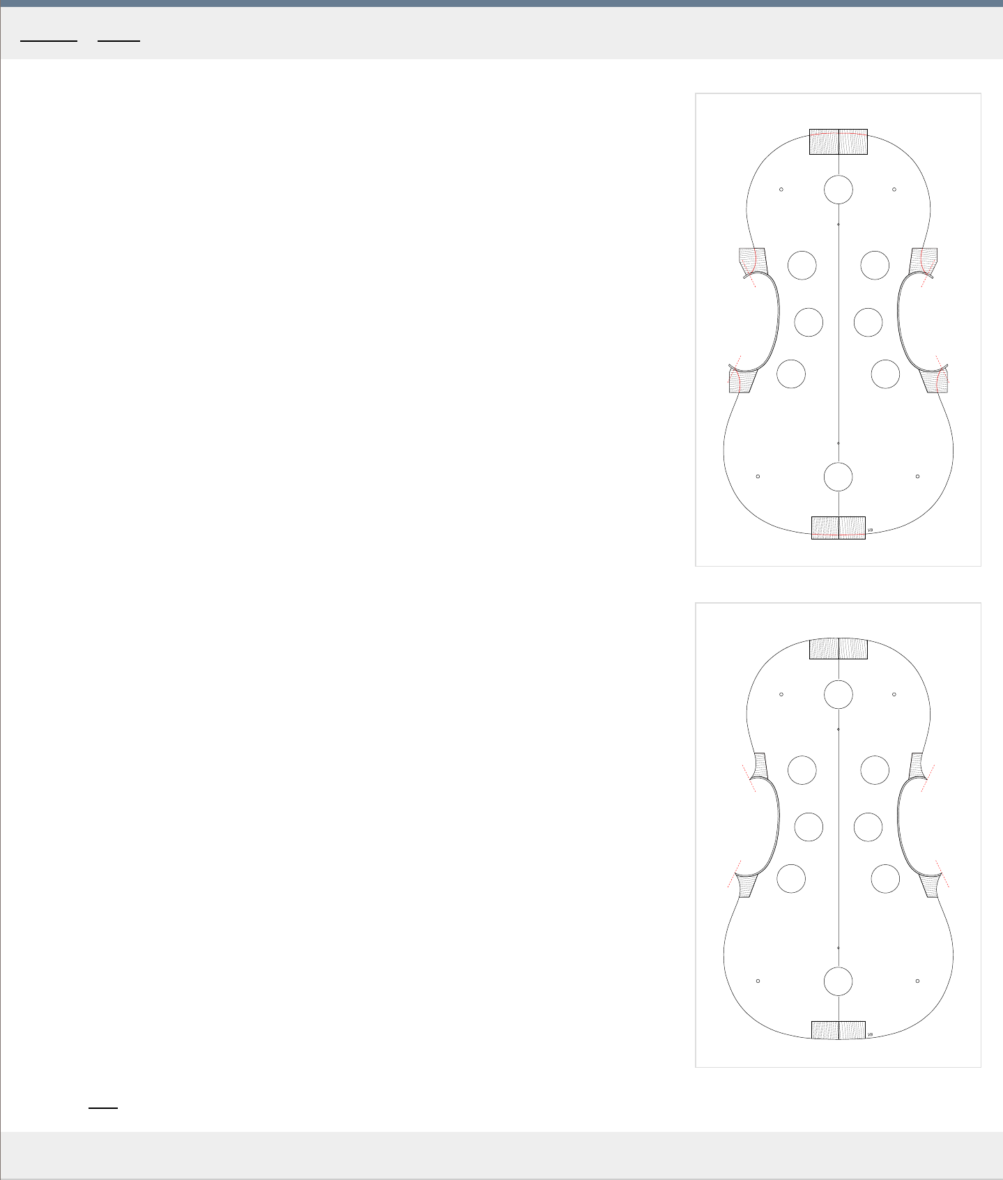
Cutting the upper and lower bout blocks
1
. Remove the four screws from the mould.
2. Remove the excess height of the ribs leaving them just a little proud of the blocks. For that
a small sharp block plane can be used. While planing, try to follow the shape of the rib to
avoid splitting the ends. R
epeat on both sides.
3. Use sanding paper on a flat surface to make the ribs flush with the blocks but don't
r
emove any material from the blocks. Now the mould should be sitting on your flat surface
without rocking.
4. As with the C ribs blocks {in the previous article}, using a suitable gouge, pare away the
wood on the upper and lower cor
ner blocks to the contour line depicted in red in Fig. 1 .
The difference here is the need to create a feathering at both ends of each C rib, see how
the r
ed line cuts into the rib.
5. Shorten the tips of the ribs to a distance where the final tips will be, in our example, the
finished tips will pr
otrude about 2 mm from the tips of the template. Observe the template
outline and determine where it will naturally cross into the tip of the rib, creating the
feathering. If you have the original or its photograph, try to determine where the tips of
the ribs end there and approximate. See the red dashed lines for suggested tips in our
example in Fig. 1 .
When cutting, make sure the tips end up at right angles to the bottom plane. For this, you
can use the sanding paper glued to a squar
e block of wood.
6. Using a suitable, sharp gouge, create the feathering, cutting across grain from top to
bottom.
7. Make the rest of the outline in the corner blocks flow naturally into the newly created
feathering.
8. You can finish the surfaces with sanding paper on a stick making everything very fluent
and smooth.
Again, the transition between the block and the mould must be as smooth as possible. Use
your fingers to check for that.
Check often that the newly created walls are perfectly perpendicular to the workbench.
9. Cut the top and bottom blocks, again to the red line as depicted in Fig. 1 . F
inish using
sanding paper on a square block of wood.
10. Reapply soap where it might have gotten sanded off.
See
Fig. 2 for how everything should look like when finished.
Category: Ribs
Home - Ribs - Cutting the upper and lower bout blocks
1
A1
B1 C1
B2 C2
A2
2
A1
B1 C1
B2 C2
A2
MakingTheViolin.com
The top ribs can be made of two parts and there is no need to precisely pair them as with the
bottom ribs. The ensuing gap at the top should not exceed 9 mm though. See the small gap
at the top underneath the top clamping block in Fig. 2 for an example. Also see the exploded
view in Fig. 1 to realize by how much the top and bottom ribs extend the feathered ends of
the C ribs at this point to get an idea how long you should cut them before bending.
Bending the ribs
For the bending itself the same rules as for the C ribs apply. If you need bending tips, check
the chapter Bending the C ribs
.
1. Screw the four screws again in the mould again so that they rise the corner blocks about
1.5-2 mm above the surface of your workbench. Again try to put the rib stock right next
to the cor
ner blocks checking that it overlaps the corner blocks by 2 mm at the bottom
and 2+ mm at the top.
2. Cut the ribstock to correct lengths and decide the orientation of each piece, depending on
the flame. W
ith the bottom ribs, if the flame is slanted, you need to make them in two
pieces to match the slant of the rest of the ribs on both sides {mirroring}.
3. Bend the ribs. Again, for bending tips, see Bending the C ribs
.
4. Let dry.
The bottom seam
If you chose to mak
e the bottom ribs in two parts, before gluing, you will need to make them
fit as perfectly as possible. The seam must be at right angle to the bottom plane and must be
aligned with the centerline of the violin.
1
. Let the ribs be clamped at the lower corner blocks (B1
and C1) and mark the center plus 1
mm at each of the two ribs.
If you have a perfectly flat surface to rest the mould on, use a square to mark the lines
wher
e the ribs will be trimmed.
2. Trim the ribs and check how the ends align with each other. The goal is to make a seam
that is bar
ely visible. To make adjustments, you can use a small shooting board and a
block plane, your knife or a flat file.
3. Keep aligning until the ends meet well.
The clamping
F
or the whole job you will need 6 C-clamps in positions marked in red, see Fig. 2 .
1
. Notice the 6 clamping blocks "A1, B1, C1 and A2, B2, C2" in Fig. 1 which ar
e made of
hard wood with the sides touching the ribs following the curvature as closely as possible.
Also, the sides touching the ribs are padded with something soft {ie. leather} to ensure
the best contact possible without harming the ribs.
2. Again, as with the C ribs, the red arrows in Fig. 2 denote wher
e the clamps` action should
be. Before gluing, try to clamp down the ribs in their final positions to ensure that
everything sits well and that there are no gaps anywhere.
Gluing the bottom ribs
1. Optionally, preheat the block you are about to glue to get more working time.
2. Put some medium thickness glue on the bottom block "A1" , align the lef
t rib with the
violin center and hold down with your thumb. Take the right rib along with the clamping
block, position quickly to create the perfect seam, hold with both your thumbs for about 10
seconds, slide the clamping block in position and clamp down. Check that the ribs still
match perfectly and that they stand firmly on the workbench overreaching "A1" block on
both sides by at least 1-2 mm .
3
. The same goes for the "B1, C1" cor
ner blocks. Put some glue on the "B1" cornerblock and
running your fingers from the already glued "A1" block up to the "B1" block make sure
there are no gaps between the ribs and the mould and that the rib rests on the workbench.
Clamp swiftly.
4. Repeat with the "C1" block.
Gluing the top ribs
1. Here you can start the gluing from the upper corner blocks "B2"
and "C2" going up to the
top "A2" block. The procedure is otherwise the same as with the bottom ribs.
Category: Ribs
Home - Ribs - Gluing the top and bottom ribs
1
A B
C D
2
D
MakingTheViolin.com
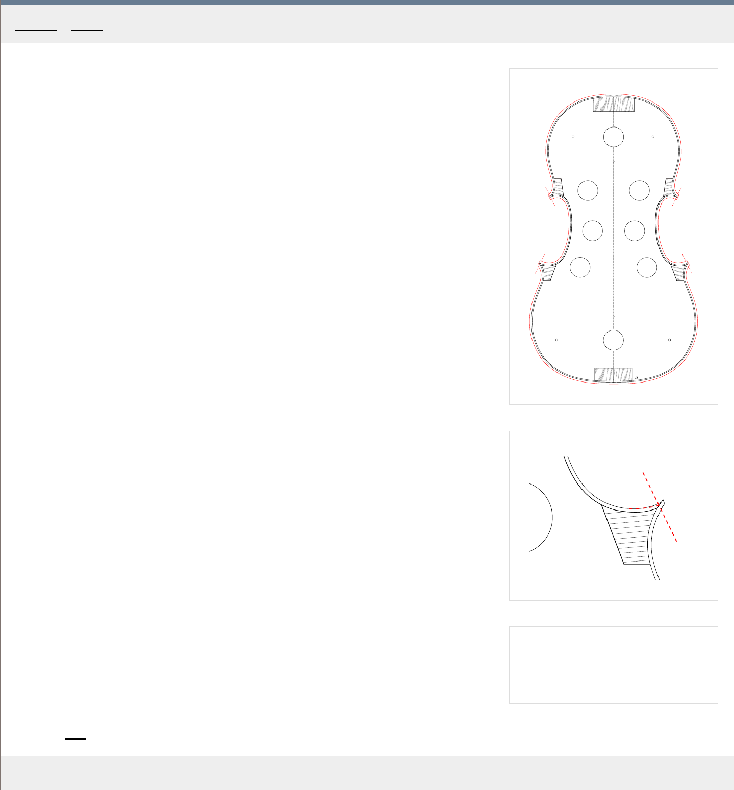
Finishing the corners
1
. Remove the four screws from the mould again.
2. Plane down the heights of all the ribs on both sides, leaving them just a little proud (.5
mm) of the blocks. When planing, follow the outline of the ribs with your block plane to get
a smooth cut.
3. Measure the span of the upper "A-B"
and lower "C-D" corners and compare it to the
original violin. If you have got the original plate outline printed out you can also now try to
align the ribs over it and check this way how close you are to the original. See the red
plate outline in Fig. 1.
The final ends should ideally be where the feathered C bouts end.
4
. Determine where the final tips should be and mark them at the top of the ribs. See the red
dashed lines in Fig. 1.
5. Using your razor sharp knife, trim the upper and lower ribs` protruding ends so that they
e
xtend beyond the previously made marks by about 1 mm . See Fig. 1. Be very careful
not to chip the ends - when you are getting near the end of the cut, stop and finish the cut
from the opposite direction.
6. If the final ends don't coincide with the feathering, see the paragraph below for possible
solutions.
7. Make the ends of the ribs flush with the feathering using an abrasive paper block. Make
sur
e the tips are at right angles to your flat surface (workbench).
8. Use the sanding pager of your flat surface to make the ribs level with the blocks, on both
sides. Y
ou should still be left with the rib height a little (.5 mm) higher than the final
heights.
In case you're a little off
If the tips of your ribs are still too wide and you have already reached the feathering, you can
still reduce their width but the thickness of the C bouts at their feathered ends will also have
to be reduced, because at the very ends of the corners, the thickness must still remain that of
the ribs, which is about 1.1 mm, not more. In Fig. 2. you see this done for the lower right
corner "D" . The red dashed lines denote the material removed.
If, on the other hand, the feathering is inset too much and it doesn't reach your projected tips,
you will need to shorten the tips further to reach that feathering even if it means the resulting
violin will be a little narrower at the corners.
Category: Ribs
Home - Ribs - Finishing the corners
1
2
3
MakingTheViolin.com
Creating the strips
1
. Create spruce or willow strips 7 x 2 mm
, ideally about 40 cm long. The wood grain should
run parallel with the length. Both horizontal and vertical grain can be used.
To thickness the strips, use your regular blade block plane, clamping down the one end of
the strip to your workbench. See the Thicknessing section in
Preparing the ribs for
thicknessing tips.
Make sure the thickness of 2 mm is maintained all over the strip, as thick
er strips are
difficult to bend and thinner aren't firm enough.
Cutting the mortices
The mortices are to be cut 2 x 7 x 7 mm into the top, bottom and C bout side blocks. For
this, use a sharp knife and also preferably a 1.5 mm wide chisel. Notice that the mortices are
cut for the C linings only, see Fig. 1.
1
. Mark the 7 mm length and 7 mm depth lightly on the blocks using a compass.
2. Cut the wall of the mortice opposed to the one adjacent to the rib to about 3.5 mm depth,
using your knife.
3. Cut the end wall of the mortice using your narrow chisel.
4. Cut the bottom of the mortice using your narrow chisel and scoop out the material.
5. Cut the wall again to the final 7 mm depth.
6. Cut the end wall of the mortice using your narrow chisel, finishing it.
7. Cut the bottom of the mortice using your narrow chisel, scoop out the material and finalize
the mortice.
8. Repeat with the remaining C blocks and on the other side.
Bending, fitting & gluing
1. Bend the strips on your bending iron as you would the ribs and cut them to required
lengths. If the outline of the ribs is perfect, the linings should be a perfect fit, no gaps
whatsoever should be pr
esent. Any gap will tend to alter the rib outline quite significantly.
This can be used to your advantage, if the outline of the ribs needs corr
ecting. Leave a
small gap where the ribs need to be less curved, clamp with your fingers and see how it
affects the outline. See Fig. 2. for correctly fitted linings, here in red.
1. After you have fitted all the linings, clamp them using rubber band reinforced clothespins
and let dry. Take a look at Fig. 3. to get an idea of the distribution of the clothespins.
Gluing
1. Work in parts, remove the clothespins holding one lining.
2. Preheat the part to get longer working times.
3. Apply medium thickness glue to just the lining. In case of C linings apply also some glue in
the mortices.
4. Put the lining in, make sure it is perfectly flush with the ribs and reclamp with the
clothespins as quickly as possible. Again, mak
e sure the lining remains flush with the ribs.
Category: Ribs
Home - Ribs - Linings
1
2
3
MakingTheViolin.com
Finishing the rib structure
1
. When the linings have dried, sand the whole rib structure down on both sides to the final
heights, ie. 32 mm at the bottom and 30 mm at the top /Messiah/.
2. Glue size the ends of all blocks with thin hide glue.
3. Finish the corners up to the tips using a fine file and sandpaper on a stick.
The rib structure is almost finished. F
or now , you should leave it on the mould to
prevent warping. The remaining steps in this chapter are carried out after the top
and back plates have been finished. If you are ready to start on the front plate,
refer to the next chapter called Front
.
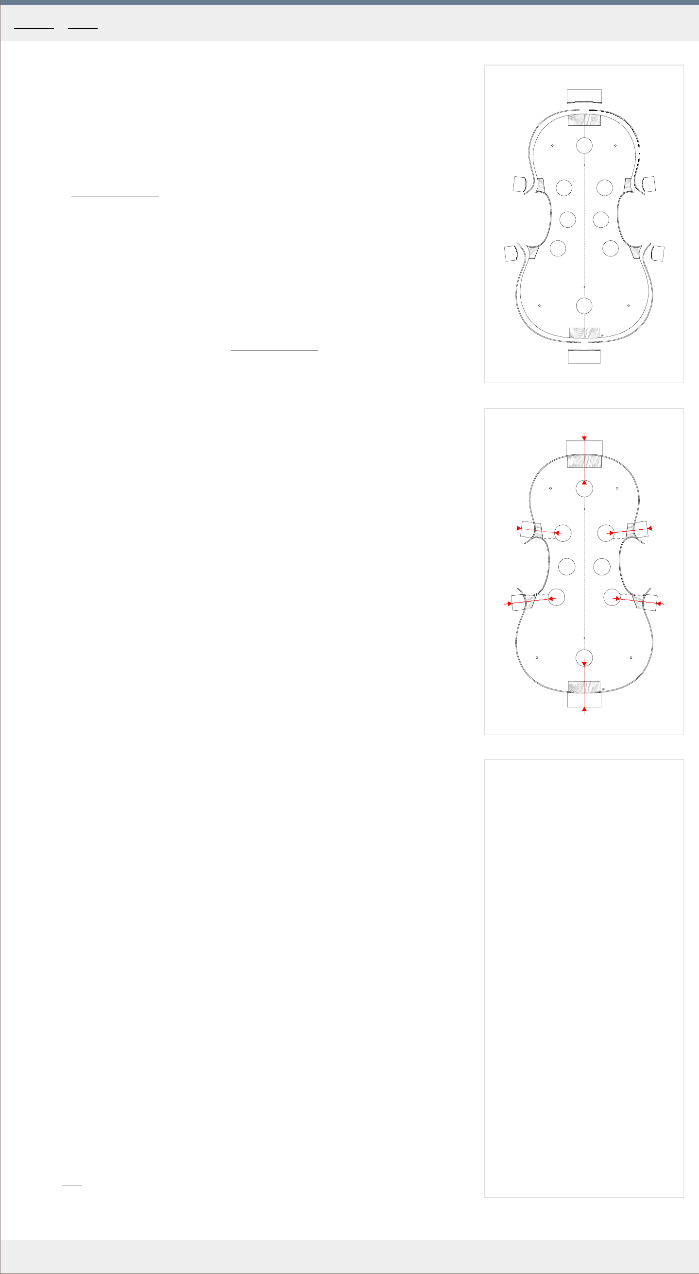
Removing the ribs from the mould
1. Mark distinctly the top of the rib structure, so that later you are able to tell the top-bottom
orientation.
2. To snap the blocks free of the mould, put your fingers where the red ellipses are in Fig. 1.
to serve as a kind of safety bed and tap lightly with a small hammer on the opposite side,
on the block, see r
ed arrows in Fig. 1 .
3. Repeat with other blocks, until the whole rib structure is unglued.
4. To slide the ribs off the mould, hold the ribs in the waist and spread them so that the upper
and lower cor
ner blocks are completely outside their mortices, resting on the edges, see
the red arrows pointing to those places in Fig. 2 . Of course, you need to be careful not to
break the rather fragile structure, the top and bottom spruce blocks are sometimes also
prone to splitting.
5
. Now you should be able to remove the ribs from the mould starting with the bottom block,
working your way up.
6. Inspect and carefully remove any excess of glue. Check the ribs for any missing
parts/splinters that may have br
oken off/gotten stuck to the mould. Reglue if necessary.
Trimming the blocks
1. Put the ribs on a flat surface and take a look at the shapes of the top and bottom blocks in
Fig. 3. . If you want, you can mark the r
ound outlines to guide your cutting.
2. Using a sharp chisel trim the top and bottom blocks. Work gradually, the first cut being
always small to r
ead the splitting angle, to allow for corrections in case the wood splits
unevenly a make sure the newly created walls are perfectly perpendicular.
The final thickness of the top block "a" is 18 mm , and of the bottom block "b" is 16 mm .
3. Use a shallow gouge for the cornerblocks.
See Fig. 3. for how the finalized blocks should look lik
e.
4. Inspect the blocks again making sure there are no splinters or loose parts that might cause
buzzes later on. F
inish with sanding paper, if you wish.
Shaping the linings
1. Take a pencil and draw a guiding line in the middle of each lining along their length.
2. With a suitable sharp knife start cutting the lower half of each lining leaving the bottom
about 0.5 mm thick. See the "1" pr
ofile in Fig 3. for reference.
3. Smooth the resulting "hump" with a scraper to create a good beveled surface as in "2" .
F
inish with sanding paper, if you wish.
You should inspect the whole structure again to see there are no loose pieces of wood or
splinters which might later cause buzzes in the finished instrument. Also check that
everything is glued together and that there are no gaps.
If you need to store the ribs elsewhere, put it somewhere with constant humidity, preferably
about 50 percent, and room temperature.
The weight of the finished ribs should be about 50 grams .
Category: Ribs
Home - Ribs - Finishing the rib structure

a
d
c
Front
MakingTheViolin.com
Home - F ront
1. Preparing the wood for the front plate
2. Marking the front plate outline
3. Shaping the plate corners
4. Sawing the front plate outline
5. Finalizing the edge thicknesses and creating the platform
6. Marking and cutting the purfling channel
7. Bending and gluing the purfling
8. Arching
9. Marking and fluting the F-holes
10. Hollowing and thicknessing
11. Cutting the F-holes
12. Bass bar
1
A
B
C
D
2
3
A B
4
A
B
5
6
C
7
8
MakingTheViolin.com
Choosing the wood
The wood for the front plate should be as flawless as possible.
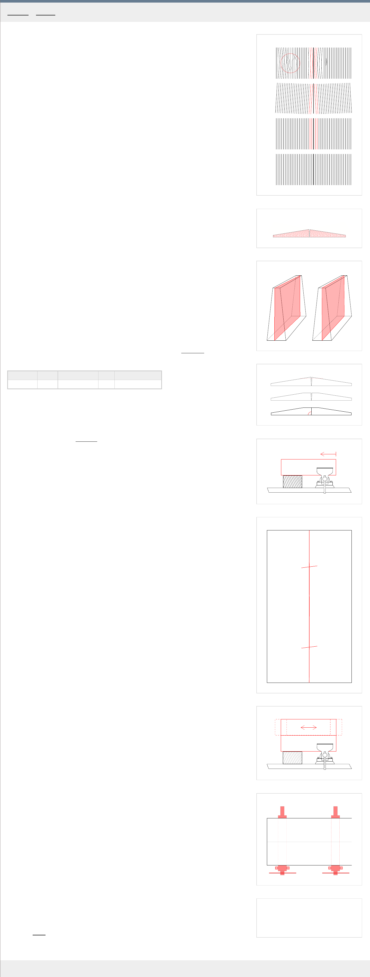
1
. Check that the wooden billets have sufficient dimensions for the violin you are building.
2. Check for the following errors: Fig. 1. , points "A-C" for possible er
rors.
a) In point "A" you see an assortment of twists and warps as well as a r
esin streak.
b)In "B"
the growth lines are straight but the gluing surfaces have to be planed to make
the lines parallel with them.
c) In "C" you see the staining caused in most cases by o
xidation. You may or may not be
able to planed it off depending on location and size.
d)
In "D" everything is cor
rect.
3. See that the billets are correctly quartersawn, which means that the growth lines should
look lik
e in Fig. 2. when looked at from the side. (sometimes the cutting marks from the
circular saw may interfere with the reading of the growth rings. Shave off the marks with
you block plane to get a clear view of the rings) Making sure the wood is correctly
quartered is especially important if you get the wood in precut billets where any
corrections are almost impossible. Badly quartersawn wood with growth lines not going at
right angle to the bottom plane is structurally much less stable.
4
. The runout is a deficiency in wood which is one of the most difficult to indicate. It happens
when the cut of the wood is not in perfect alignment with the natural run of the grain. That
is why the best wood with no runout should always be split rather than cut. See Fig. 3 for
illustration. The r
ed planes depict the natural grain. In "A" the natural grain is misaligned
with the billet, indicating that there is a runout. If there is no runout, the billet should split
through its center, along the red plane as in "B" . A little runout is usually not a problem,
but more of it may negatively affect the structural integrity of the wood.
5
. If you want, you can also check the growth line density. It can vary throughout the piece.
Some gr
eat violins have it ranging from medium {1-1.5mm distance} at the edges of the
plate to dense {0.5 mm} at the center. Dense growth lines all over usually mean denser
wood which you should probably avoid. Look at the growth lines in the wood of the violin
you are copying and try to find similar wood if you are aiming for similar sound.
It is also helpful to make a note of the specific gravity of the pieces you chose and better yet,
make a table which will list the parameters of the woods used as you progress from one violin
to the next for reference. Check the Specific gravity calculator in the Materials
section. You
can create a table like this one:
Violin no. Wood Source Date Specific gravity
1 Spruce Andreas Pahler 2003 0.41
Numbers around .42 for spruce and 0.55 for maple are considered good.
Preparing the wood
If you decide to cut the bass bar from one of the halves before joining them together,
refer to the chapter on the Bass bar
for the dimensions.
1. Plane the chosen pieces flat on the bottom side, check for rock on your flat workbench.
2. Put the pieces together and plane the upper tops to see clearly where they meet. Be
car
eful not to remove too much wood as at the top the plates should still be thick enough
to accommodate the height of the finished plate. See next Fig. 4. Make sure that the
pieces put together have sufficient height both at the sides and at the projected center
joint. The violin we are building here has the finished belly height of about 16 mm, so with
a safety margin, the pieces should be about at least 20 mm high.
3
. Plane the sides at right angles to the bottom surface using preferably a jointer plane {no.
6 plane}. T
o do that, clamp one end of the piece in the vice and support the other with a
block of wood to make sure the piece won`t bend while planing. See Fig. 5.
Check the edges with a square. Both edges must be at right angles to the bottom surface
along the whole length. No twist.
4
. Make sure the growth lines run parallel at the center. Make any corrections now, before
you finalize the joint in the ne
xt step.
5. Bring the two edges together and check for gaps and rock. Use a source of light positioned
behind the joint to see how the surfaces match up. If the surface is a little convex
(lengthwise), push down during planing a little mor
e at the center to correct that. Special
attention should be paid to the extremes, which should be in perfect contact up to the
ends.
6
. Optional: Put your sash clamps in place and test clamping down the billets. The join
surfaces must be in perfect contact, with no visible gap, when the billets are fully clamped.
If they ar
en't its either you didn't prepare them well enough or the action of the clamps
may be wrong. In that case, try to correct (by planing) the outer sides of the billets (those
which run parallel with the gluing surfaces), to compensate.
7. Lastly, before gluing, make two vertical marks on both pieces, crossing the joint, using a
pencil. This will help you cor
rectly align the top piece quickly and precisely when the glue
starts "biting". See the two short horizontal lines in Fig. 6.
Because the wood tends to "move" with the changing humidity and temperature in your
workshop, it is recommended to glue the pieces together right after you have achieved a
good fit.
Gluing the pieces together
1
. Put one piece in the vice with its gluing surface up. See Fig. 7.
Y
ou should rise the temperature in your workshop or use a heater to heat up the pieces, to
prolong the working time of the glue. Do not heat up the pieces too much or unevenly, as
that will cause the glue to penetrate the wooden surfaces unevenly, with very high
penetration in hot areas, resulting in a starved joint. So a joint that has 30C evenly
distributed is ideal.
2
. Using a larger brush, apply ample medium thickness hide glue all over the gluing surface
on both the clamped piece and the other one (you ar
e holding in your other hand) as fast
as possible.
3. Put the gluing surfaces together and rub vigorously back and forth, while still maintaining
full contact of the surfaces, pr
essing down, squeezing out the glue. See Fig. 7.
4. When you feel the glue starts "biting", finish the move and align the surfaces as precisely
as possible (mak
e the previously made marks meet).
5. Optional: Let dry for 30 seconds, then carefully lay down on the prepared sash clamps and
clamp down lightly as in Fig. 8.
6. Clean up and let dry over night.
Category
: Front
Home - F ront - Preparing the wood for the front plate
1
A
B
x2
x1
2
A
B
x2
x1
3
A
B
MakingTheViolin.com
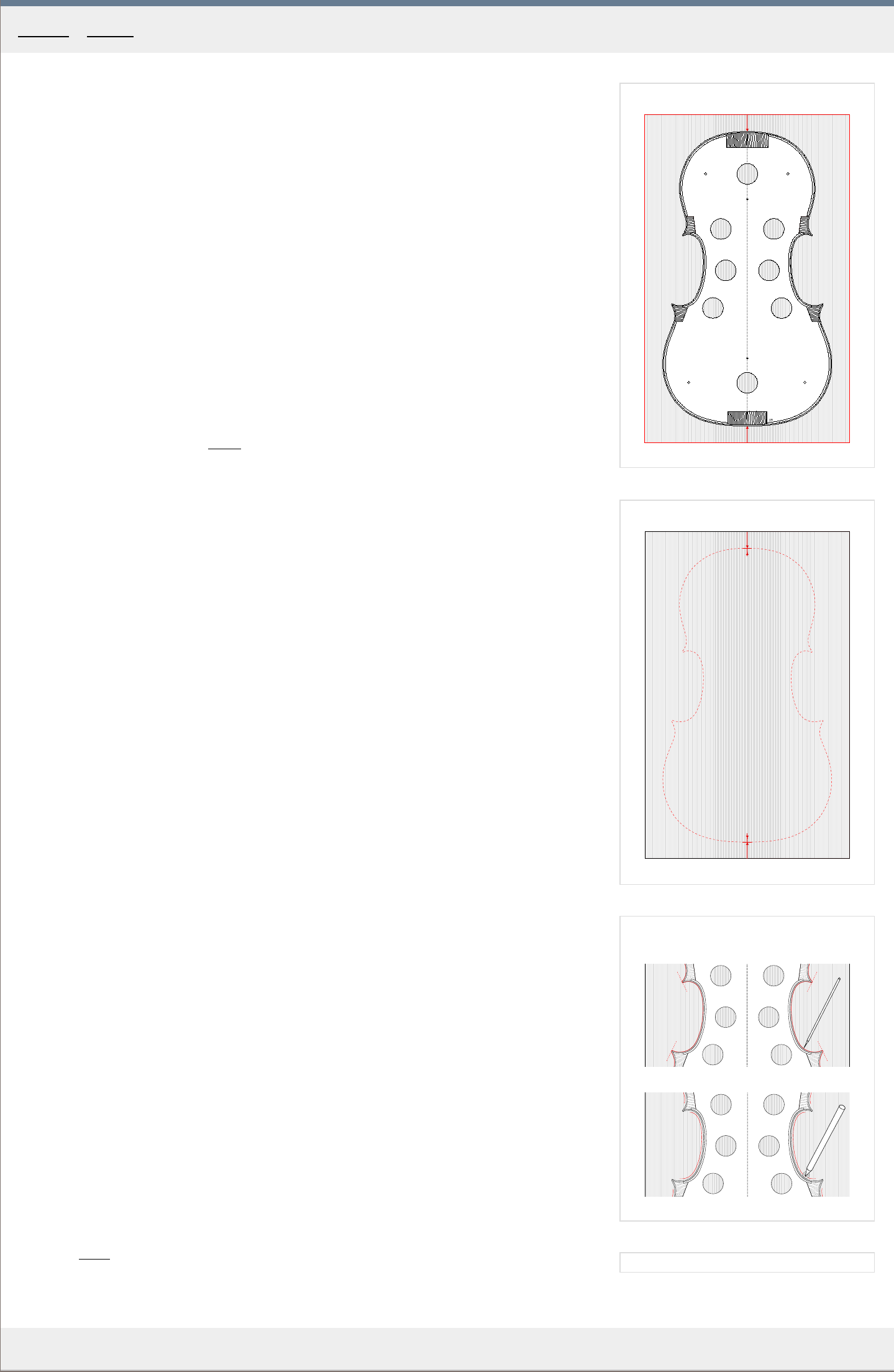
After the plate had dried, check the bottom side with your straightedge. If the bottom is
uneven, you will have to plane it perfectly flat so that the ribs are in full contact with it.
1
. Remove all excess glue and clamp the plate down on your workbench. If you have a
workbench with dogs, use those to fix the plate upside down. Or you can use sash clamps
to hold the plate and clamp the sash clamps down to your workbench.
2. Make the bottom perfectly flat using your long plane. Be careful of the wood grain. The two
billets' grain runs in opposite dir
ections so you will need to keep flipping the plate
frequently to go with the grain to avoid tearing. The tearing is more likely with highly
flamed maple. Tilting the plane sideways a little or going accross the grain should help too.
If nothing helps, use the scraper blade.
3. To remove little tearing caused by planing and achieve perfect flatness, you can sand the
bottom on your flat sandpaper glass surface (you used this to finalize the rib height).
Fixing the ribs to the plate
Now you need to fix the ribs to the plate in or
der to transfer the actual outline. If at this
point you are also transfering the outline to the back plate, do not forget to
include the button. See the Back
chapter for its dimensions.
1. On the ribs, remark the centerline, if necessary.
2. Take the ribs and put them on the front plate facing upside down. Align the centerline on
the ribs with that on the fr
ont plate. See Fig. 1.
3. Mark out the very top and bottom of the ribs, drawing a 1 cm long line, at the centerline of
the plate. See points "A and B" in Fig. 1.
4. Remove the ribs and on the centerline of the top plate, scribe another pair of marks, about
4 mm inwar
ds from the top and bottom marks "A and B" you have just made. See Fig. 2.
The red dashed line just shows for illustration where the ribs were placed.
5. At those two points, drill through two holes, 1.5 mm in diameter, at right angles to the
plate.
6. Put the ribs back on the front plate in exactly the same position as before {par. 2}, clamp
down sufficiently and drill two 5 mm deep holes into the top and bottom rib blocks using
the pr
eviously predrilled holes as guides.
7. You can now plug into the holes two 1.5 mm drill bits as locating pins to k
eep the ribs
positioned on the plate. With the bits in place, you can remove the clamps and start with
the outline.
Marking the outline
Make sure the outline of the ribs is flawless, the corners are finished.
1
. Using a sharp scribe, mark the whole outline of the ribs on the plate. Make sur
e you also
mark distinctly the ends of the ribs at the corners, but don't make the mark too deep as
this will stay on the finished plate. See "A" in Fig. 3.
2. Now you need to draw the second outline which will delimit the shape of the top plate and
which should be outset by about 2.5 mm fr
om the ribs, depending on the overhang on the
original violin. For this choose a washer, which you know will offset the contour by the
distance needed. Using a sharp pencil draw this parallel line around the ribs, but always
stop about 1 cm short of the tips of the corners. See "B" in Fig. 3.
Make sure you hold the pencil at a constant angle as different angles may produce
different distances. Make a couple of tests, to get the idea as to what kind of line the
washer and the pencil produce.
3
. Remove the locating pins and take the ribs off the plate.
Category
: Front
Home - F ront - Marking the front plate outline
1
x1
x2
MakingTheViolin.com
Shaping the corners
The shapes of the corners must now be reconstructed by hand. They are one of the focus
points on the violin and naturally they attract a lot of attention. Their proper execution is
therefore very important.
1
. It is helpful to construct for each corner a guideline by projecting the angle of the original
violin cor
ner`s tip towards the centerline at points X1 and X2. These points can then be
transferred to the new plate to help project the new corners. See the red dashed lines in
Fig. 1.
2. Mark the tips about 2 mm beyond the tip of the rib.
3. Finish the radii in accord with the original width and general shape of the corners.
Notice how the distance of the outline from the ribs increases especially with the wider
lower corners.
The newly created corners are depicted in solid red in Fig. 1.
Category
: Front
Home - F ront - Shaping the plate corners
1
2
A
B
D1
D2
3
A
B
C
D
v
v
MakingTheViolin.com
Fixing the plate
1
. Fix a wooden plank (in red in Fig. 1. ) of appr
oximately 60 x 7 x 5 cm to your workbench
making sure its protruding by at least 30 cm .
2. Clamp your front plate upside down to the bottom of this plank. See the top-down view of
the setup in Fig. 1.
Cutting the plate
1. Using a coping saw, cut within 2 mm of the outer pencil line. Mak
e sure the saw is tilted a
little away from the outline so that you avoid undercutting. Keep rotating the plate as
necessary.
2. Correct the outline using a rasp, downstrokes only, so as to avoid tearing off the fibers at
the bottom of the plate. Get to about .5 mm outside the outline.
3. Using a marking gauge, scribe along the whole length of the contour a line 6 mm in
height.
The plate holder
Now is the time to attach the plate to the plate holder
. It serves to hold the front and back
plate while you carve the outside arching and do the purfling.
1
. Get a piece of wood about 60 x 30 x 2 cm.
2. Mark the centerline, take the template you started the violin with and scribe the full violin
outline on the plate holder
.
3. On the centerline drill two holes about 12 cm in fr
om the top and bottom edges of the
outline. Refer to Fig. 2. for their position.
4. Find two screws and insert them in the holes from the bottom side to find out by how much
they pr
otrude. They must not stick out more than 8-9 mm but also not much less in order
to securely hold the plate. Use washers to reduce the length of the screws if necessary.
Fixing the plate to the plate holder
1
. Put the plate bottom down on the plate holder and align it with the centerline. Refer to
Fig. 2. to see how the plate is fix
ed to the holder.
2. Clamp down securely with a few clamps.
3. Flip the holder and screw in the two screws.
Make sure again that the screws will not enter the wood farther than 8-9 mm to avoid
penetrating into the wood that will be in the finished plate.
The holder must hold the plate firmly but avoid over-tightening.
4. Remove the clamps and clamp down the holder to the workbench.
Removing wood
1. With a pencil, mark out the outer "A
, B, C, D" areas as depicted in Fig. 3.
2. Using a suitable gougle, pare away the wood down to the 6 mm height-line, you
pr
eviously created. Make sure you do not "enter" the waist "v" of the plate more than 15
mm.
Take a look at the red arrows in Fig. 3 to see the general direction of carving.
As you continue removing wood be extremely careful in the area of corners, as these are
easily split off. Be e
xtra sensitive of the grain in those areas and apply only very limited
force. See the red arrows near the corner in Fig. 3 for the direction of carving. Also make
sure your gouge is razor sharp.
Category: Front
Home - F ront - Sawing the front plate outline
1
MakingTheViolin.com
Finalizing the outline
1
. Now is the time to finalize the outline of the plate. Clamp upside down onto the plank as when
you wer
e cutting out the outline and using a file {downstrokes only}, make sure the outline is
even, smooth and true to the overhang, about 2.5 mm in our case. Leave the corners a little
wider than marked.
2. Again, using the marking gauge, mark the height, this time of 4.5 mm , all the way ar
ound the
plate.
3. Using a shallow gouge remove the wood along the edge farther down to the marked line. As
pr
eviously, be very careful in the area of corners. Always go with or across the grain, never
against. Refer to the Fig. 3. in the previous chapter for cutting directions.
4. According the Fig. 1 mark a line along the whole cir
cumference of the plate, see the red
dashed line, 7 mm in at the waist and 9 mm in at the upper and lower bouts. This line will
serve to limit the scope of the platform. The marking is best done with a compass, its needle
following the edge of the plate.
Creating the platform
1
. Using a narrow chisel, make a series of vertical incisions along the red dashed line in Fig. 1
not going too deep into the wood. Be car
eful in areas where the grain runs parallel to the
incisions allowing the gouge to enter the wood easily.
2. With a shallow gouge and finally a flat chisel remove the wood and create the platform. Also,
see the pr
ofile of the finished platform below.
3. Even out the platform using a file, if necessary. Check for flatness and also for consistent
thickness of about 4.2 mm.
4. Take the purfling cutter and make sure its passage is unblocked by any wood, especially in the
waist ar
ea.
Category: Front
Home - F ront - Finalizing the edge thicknesses and creating the platform
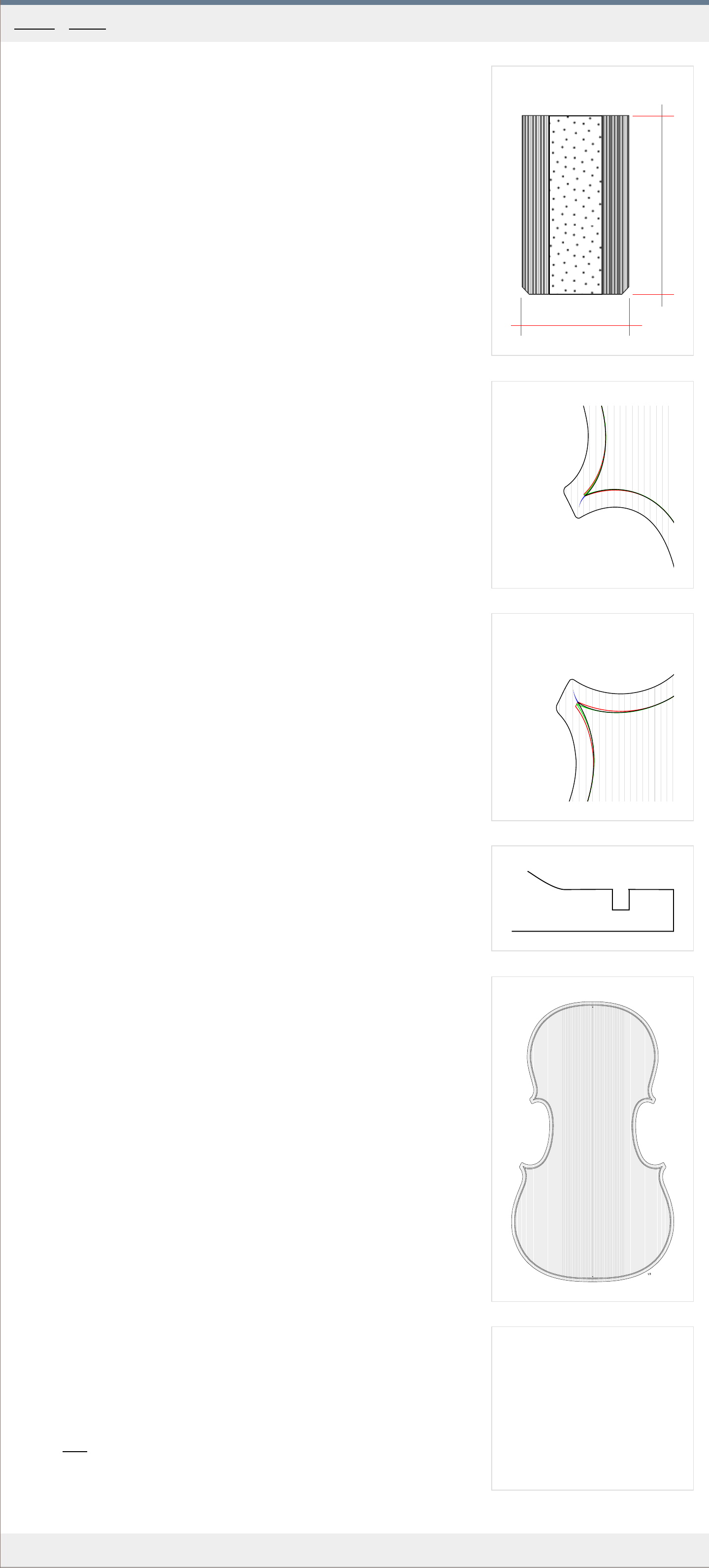
1
A
B
2 mm
1.2 mm
A
2
3
4
5
MakingTheViolin.com
The purfling
The purfling is the inlay which runs around the edge of the top and bottom plate. It is usually
a "sandwich" of three sheets of wood glued together. Other materials such as hardened paper
are also used today as the cheapest options but these should generally be avoided. In Fig. 1.
you can see the three distinctive layers comprising the inlay of total thickness of 1.2 mm .
The "A" layers are 0.3 mm and the "B" layer is 0.6 mm thick. In the olden days, the bright
layers might have been maple and the dark one ebony shavings. Today, most makers buy the
purfling strips premade.
1
. Make sure the thickness is even, typically about 1.2 mm and the height is about 2 mm
thr
oughout.
2. Create a slight bevel at the bottom edges to allow for and easier insertion into the
channel. See Fig. 1.
Marking the purfling channel
1. Make sure again that the plate outline is perfect, without any bumps and that it flows
gracefully and naturally in accor
d with the violin copied as well as with what you consider
natural.
This outline will now serve as the guideline for the purfling marker and ther
efore for the
purfling channel itself. Remember that the final overhang is about 2.5 mm for the violin
we are making, except for the corners, so finalize the outline just a little over that.
If you leave the overhang too large now, the purfling will follow it, making any reduction
later very difficult.
2. Carefully observe the distance of the purfling channel from the edge in the copied
instrument. Nor
mally it is about 4 mm in but its final position is also influenced by the
length and width of the top and bottom corners. The purfling mitres must meet at just the
right position to form the tip and the bee sting.
The corners are constructed as in Fig. 2 and 3. The r
ed line indicates the outline linearly
inset by 3.7 mm . The green line shows the lines altered so that they form a sharp tip and
meet at the correct distance from the corner`s end. The black line is the final
approximation taking into account the preference that the purfling in the corners should be
leaning a little, following the bee sting. The bee sting itself is in blue and flows naturally
towards the corner of the corner.
3
. Now you need to set up your purfling marker based on the previous observations. If using
a double edge mark
er, make sure the width of the resulting channel is enough for the
purfling to slide in easily. When gluing, especially with spruce, the wood tends to swell, and
any tight fit now will become impossible then. To test for that, use a piece of spruce, make
a series of marks and cuts, scoop out and see if the purfling strip fits in nicely.
The position of the purfling channel in relation to the edge and the corners can be tested
first on the opposite side of the plate.
4. Everything adjusted, you can start marking the purfling channel. Especially with spruce, it
is important to first go very lightly, otherwise the blades tend to get misaligned by the
wood grain having the tendency to go along with it. It is also important that you hold the
purfling marker at a constant, perpendicular angle.
Bear in mind that you are just marking the channel, not actually cutting it, so create a
rather shallow cut but with gr
eat precision which will later serve as a guideline for the
cutting knife itself. Again, go light, or you will loose precision. Repeat, until you are sure
the groove is deep enough to guide the knife.
Now the corners. Measure the distance the tips of the purfling in the corners ends from the tip
of the corner itself. With the Messiah this is about 3.5 mm . Lightly Mark this distance on each
corner. Start lightly marking the channel in each corner always starting from the C bout side.
The lines should meet at the marked distance from the corner's tip. If they don't, adjust so
that they meet there. Remember that the tip leans a little towards the C side so the oposite
side can be shaped accordingly.
Cutting the purfling channel
The cutting itself is done with a knife. You can use your regular knife with bevels on both
sides, or you can try a knife with just one side bevelled, which makes the cutting of flat,
perpendicular walls a little easier.
Go with light strokes followed by heavier ones. Avoid undercutting - the resulting walls should
be perfectly perpendicular.
At this stage the purfling channel should be about 2 mm deep, assuming the thickness of the
plate edges is a little over 4 mm , so make controlled cuts going no deeper than that. This
depth will later get reduced, because of the fluting to about 1 mm . Consult Fig. 4 to get an
idea about the channel's position.
1
. Start cutting at the top or bottom of the plate where the grain orientation makes it easier
to mak
e precise cuts. You will cut the channel along the whole outline except for the
corners, which will be dealt with later.
2. Use a purfling pick to remove the waste material.
3. After you have finished the outline, start working on the corners. I would suggest using a
smaller knife, because it allows mor
e control in the tight curves and the bee sting.
Be extremely careful with the inner tips at the corners, which are easily chipped off,
especially in spruce.
In Fig. 5. you see the finished channel.
Category
: Front
Home - F ront - Marking the purfling channel
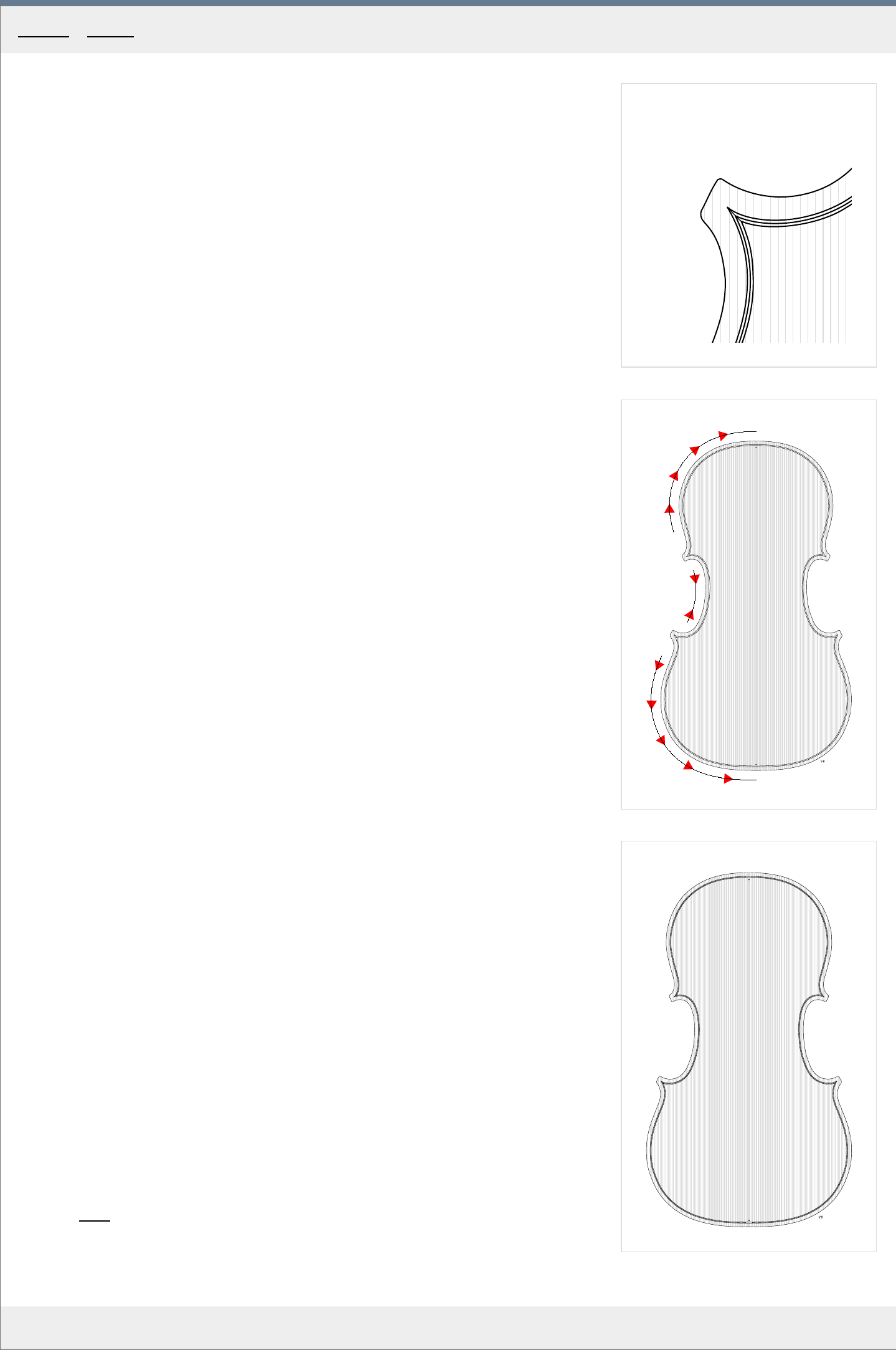
1
2
A
B
C
D
E
3
MakingTheViolin.com
Bending and fitting the purfling
You bend the purfling material as you would the ribs, using the bending iron. You can moisten
the strip slightly if it helps prevent cracking. Precaution must be taken not to overheat the
strip because the glue binding the layers together then melts and swells causing them to
separate. If possible, try the bending on scraps first.
Also, the tight curves in the upper parts of the C bouts must be bent with utmost care as here
cracking will easily occur.
On the front plate, in the upper and lower bouts, the purfling can consist of 2 parts, because
at the center it will be removed anyway. The gap must not exceed 8 mm on each side off the
center, though.
On the back plate, the upper and lower bouts should be made in one piece.
1
. If you haven't already, check that the purfling stock you will use is of correct width and
thickness thr
oughout its whole length.
2. As mentioned earlier, for an easier fit, remove the edges on the bottom side of the
purfling, making its cr
oss section look more like the letter U. See Fig. 1 in the previous
chapter for reference.
3. Start bending the strips. Once the strips are bent correctly and they fit perfectly, choose
one cor
ner, trim the ends of the strips so that they meet and fit the corner naturally. See
Fig. 1 for the detail on how the ends meet in the corner.
4. Run your finger to check that the purfling "sits" evenly along the whole outline. If not, you
may need to scoop out some mor
e wood here and there. When removing material from the
corners, again, be very careful when cutting next to the inner corner tip.
Gluing the purfling
Have a suitable smoother (something that will allow you to push the purfling into the
channel), a small hammer and a damp cloth handy. Prepare a sufficient amount of medium to
thin hide glue. As always, a warm room considerably prolongs the setting times for the glue.
Work in steps, applying hot glue into the channel first and putting in the purfling as quickly as
possible, because in a manner of seconds, the channel starts to swell making it difficult to
insert the strip. If that happens, use the small hammer and a smoother to drive it home.
The corners are always the starting points as it is crucial that the tips meet precisely. See Fig.
2 for the gluing sequence.
1
. Work in the following order:
a)
Glue the upper left corner, put in the upper left corner "A" ,
b)
Glue the the upper bout, put in the upper bout "B"
c) Glue the C bout, put in the lower corner, put in the remaining C bout "C, D"
d) Glue the lower bout, put in the lower bout "E" .
2. Go over again with a smoother to make sure the purfling is fully in everywhere.
3. When finished, remove excess glue with a damp towel.
4. Check again that the purfling is fully in everywhere.
See
Fig. 3 for the finished purfling.
Category: Front
Home - F ront - Bending and gluing the purfling
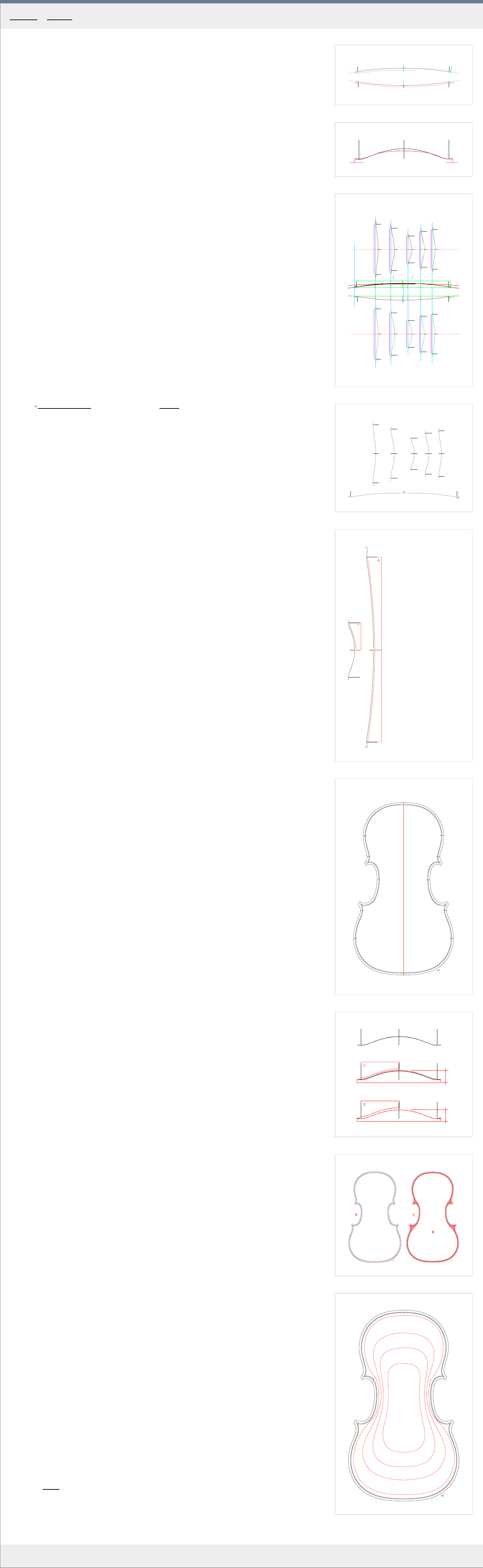
1
2
3
w131.32-h10.80
w99.7-h11.55
w157.48-h11.80
w186.27-h8.00
w146.89-h7.40
w131.32-h11.50
w99.7-h11.40
w157.48-h12.00
w186.27-h9.00
w146.89-h8.20
4
Top
5
No. 3 Mess
Back Messiah
6
A
B
C
D
E
A
B
C
D
E
F
F
7
No. 3
No. 3
arch
recurve/fluting
18 mm
16 mm
A
B
C
8
9
MakingTheViolin.com
The original and the ideal
Depending on the source model, you can either use the archings as they are, or you can
correct them. And why would you think Stradivari`s archings need any correction?
a) Structural deficiencies in the original creation. As it is in the case of Messiah, the top plate
is unusually low /only 13.8 mm/, so not copying it verbatim and making it a little higher, 15-
16 mm, is a good idea.
b) Distortions happening over time. W
ith older instruments the wear and tear over the
centuries may have caused a drop in the height of the top and bottom and subsequent
distortions may occur. You don't want to copy those, you want to give your instrument a
sound arch, which will withstand the ravages of another hundreds of years.
c) Generation loss. If you feel, lik
e I do, that you should start with a perfect design, rather
than with something that is a Nth copy of a design, think about this: 1. Concept on paper, 2.
Transfer to templates, 3. Transfer into the wood, 4. Distortion over maybe hundreds of years,
5. Tracing the old instrument`s arching on paper, 6. Transfer to templates, 7. Transfer into the
wood. As you can see, with your finished violin, you ar
e as far as 7 generations away from the
original concept, with every generation introducing inevitable errors.
The long arch
Take a good look at Fig. 1.
For the construction of the long arch in the back, a section of a circle can be used. For the top,
you can also use a circle, with the exception of the topmost platform, which should be formed
with the help of another, flatter circle /in blue/. The red lines, offset to make them more
visible, denote the original arching. The highest point on both the front and the back arching
is at the midpoint.
The cross arches
The cross sections of both the top and bottom plates can be derived from curtate cycloids.
They create perfect curves which are very close to the ones found on many Cremonese
instruments and are easily generated both by software or a simple use of a wheel, ruler and
pencil.
Curtate cycloids software download (mirror).
See Fig. 2. to see a typical cycloid shape overlaid on the existing cross arch in red /Messiah/.
Putting it all together
For the complete "remodeling" of the Messiah`s arches, according to the aforementioned
methods, see Fig. 3. The red curves denote the original arching, the black is the idealized
form.
The total body height should be somewhere about 61-64 mm .
Making the templates
Templates, especially if this is your first violin, may be of great benefit to you. They make you
work with precision you could hardly attain if you worked just by eye.
For an example of a long arch and cross arch template, see Fig. 5. These should be made of
a rigid and at the same time easily workable material. Good examples here are aluminum or
plastic, both in sufficient thickness, 1.5-2 mm depending on the material used.
In Fig. 5. , in red, you can see the physical shape of the templates. The half templates shown
here are easier done and more flexible to use than their full size counterparts.
1
. Print out the templates in Fig. 4 or photocopy the ones for your violin.
2. Glue the printouts onto the sheet of material used for the templates.
3. Cut out the templates and assign a number to each.
Carving the arching
1. Mark all the positions in Fig. 6. for the cr
oss templates so that you know where to place
them during the carving. The positions "A-E" are for the cross arching templates, the "F"
positions are for the long arch template.
You can print out the positions in Fig. 6. or use those pr
ovided with the archings for your
violin. If you want, you can also mark out these positions on your outline (half)template.
2. Mount the plate on the plate holder and fix the holder to the workbench.
3. First you need to make fit the long template. Use a small round thumb plane across the
grain and cr
eate a sort of a plateau for the long template. When the template roughly fits,
you can move onto the cross arching templates.
4. Now with frequent reference to the cross templates, start removing the wood using a
thumb plane. Blend the differ
ent positions with one another. Be aware of the general
shape of the plate. Be sensitive of the wood grain, and work with it.
5. When all the cross templates broadly fit, you can start with the fluting.
Fluting
Fluting cr
eates the re-curve in the arching. It is important both aesthetically and acoustically.
The re-curve helps the plate to vibrate more freely. See Fig. 7 . "A" is the ideal arching based
on the cycloid, "B" is the arching without the fluting, "C" is the finished cross arch.
The depth of the fluting is based on the overall height of the arch. Make only as deep a fluting
as will "land" the arch at its correct final height. See Fig. 7 .
The outer position of the fluting is somewhere in the middle between the purfling and the
edge. See Fig. 8 for reference.
Don`t try to create the fluting in one pass, work gradually instead.
Especially with spruce, be aware of the grain and always go with it.
1
. Before fluting make sure the thickness of the overhang is correct, in our case it is to be 4
mm . Go over the whole platfor
m with your marking caliper set to 4 mm and remove any
high points using your thumb plane and a file to carefully finalize the thickness.
2. Check the height of the arch at the center point with a caliper. Here its 18 mm . Checking
with the ar
ching template, I realize I will have to go another 2.2 mm lower to make the
template fit. That's OK as the target height is 15.8 mm . The depth of the fluting therefore
will be about 2 mm . See Fig. 7 for reference.
3. Mark a line using your pencil along the edge, half way in to the purfling. Fr
om this high
point line the fluting will slope towards the purfling. See Fig. 8 for the line, here in red.
4. To create the fluting use a small gauge, ie. Pfeil no. 7, tilted as in Fig. 8 . The gauge's tilt
allows for mor
e precise cutting, most of the time allowing you to go even against the
grain, if needed.
Make multiple precise passes, removing tiny shavings from the line down to the purfling.
The deepest point of the fluting (and of the ar
ching) is usually placed at the purfling or a
little bit more in. The final shape of the fluting will be defined during the scraping.
5. See Fig. 8C for the e
xtent of the fluting.
6. When all templates almost fit and the height of the arch is at about 1-1.5 mm higher than
the final height, stop using thumb planes and move over to scrapers. For various scrapers
and their sharpening see the T
ools and materials section.
Finishing
1. Start cleaning up the whole surface using a scraper.
2. If you want, you can use a way to visualize the arches better with a marking caliper. Using
a marking caliper cr
eate a number of contour lines to help you better see the irregularities
in the arching. See the lines in Fig. 9 for an example. Your lines will differ based on your
archings but they should flow gracefully.
3. Clean up the area of fluting. It is often more precise to go around the outline, touching it
with your middle finger (to k
eep it in fixed position), while holding the scraper by the
rounded tip between your index finger and thumb (kind of like holding a pen).
4. Clean up the whole surface again using a scraper, then use abrasive paper to create a
surface as smooth as possible. (The surface will later be scraped lightly yet again to bring
out the grain.)
Category
: Front
Home - F ront - Arching
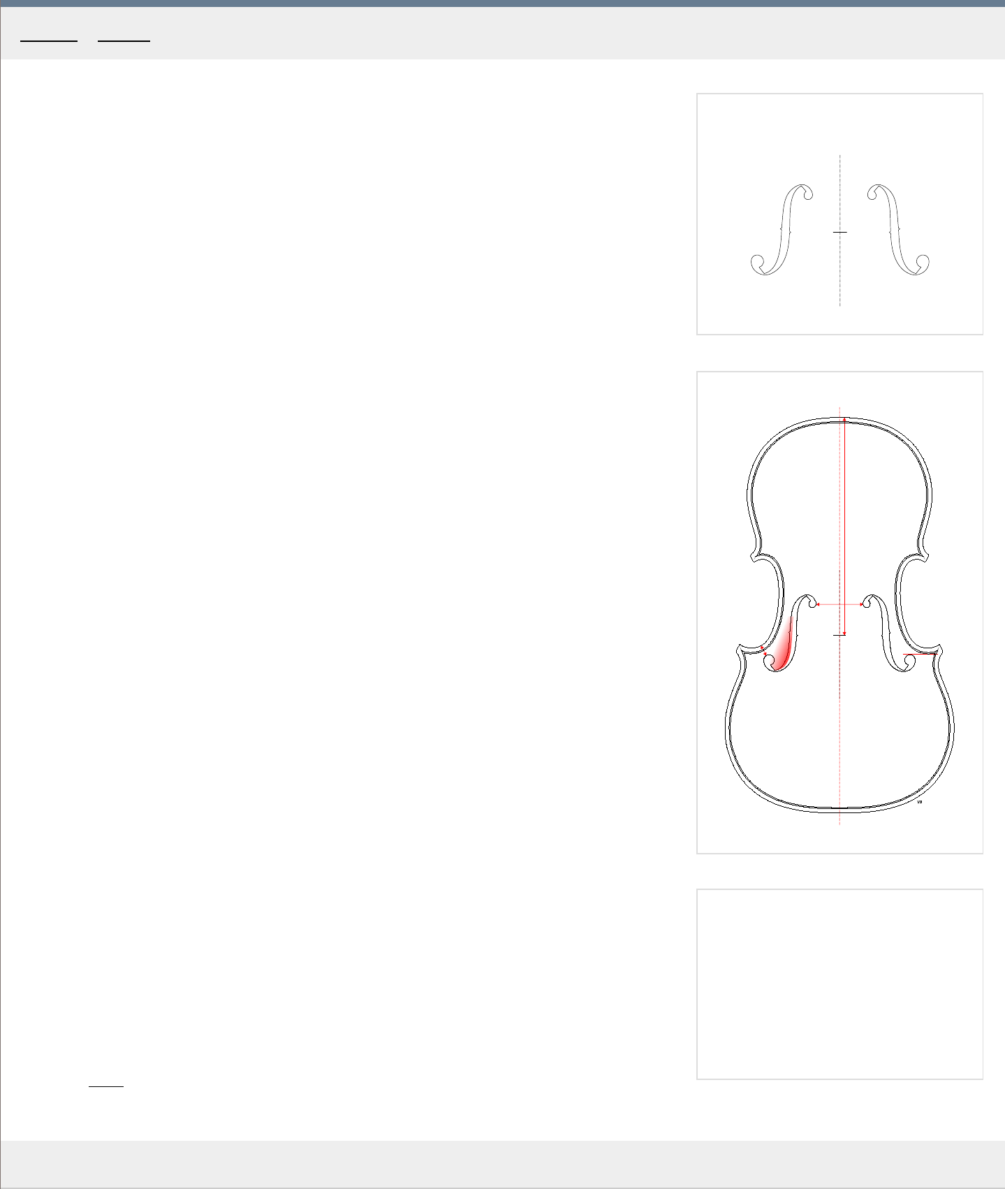
1
2
a
d
b
c
MakingTheViolin.com
Transferring the outline
After the arching on the top plate has been finished, the shape of the F holes should be
transferred onto the surface. The shape of the F holes in our example is a slightly modified
shape of the Messiah violin.
1
. Print out or otherwise transfer the outline of the F holes on a sheet of plastic foil. See Fig.
1. for the outline for the violin we are building.
2. On the printout, check that the physical measurements are correct. Ie. 42 mm distance
between the upper eyes.
3. To finish the template, take a sharp knife and carefully cut out the outlines, including the
nicks.
4. Lightly mark the stop length on the top of the violin plate, for our violin it is 196 mm . See
"b" in Fig. 2 for its location.
5. Align the centerline of the new plastic template with the centerline of the top plate and
align the inner nicks of the F holes with the stop length mark. See that the position is
cor
rect in regard to all measurements in Fig. 2 . "a" is the distance of 42 mm , "b" is the
stop length of 195-6 mm , "c" is the distance of 11 mm and "d" means the top of the
lower eye should be level with the purfling.
6
. Fasten the template in this position, with two pieces of a sticking tape, up and down, but
only lightly so that you don't tear out wood fibers when r
emoving the template.
7. Using a sharp pencil, transfer the shape of both f-holes onto the surface of the wooden
plate. When finished, r
emove the template.
Fluting the f -hole wings
In order to make the f-holes look more integral to the arching, the lower wings are fluted.
Note that the fluting gradually rises to the corner of the wing. See the red area in Fig. 2 for
reference. The red color intensity denotes (approximately) the volume of material removed. In
the area of the wing tips, you may cut as deep as 1.5 mm , depending on how "intensive" you
want your fluting to be.
1
. Use a shallow round gouge, pare away the wood in the direction away from the tip of the
wing.
2. Smooth and blend the newly created surface with the rest of the arching using your
scraper
.
3. Repeat on the other f-hole.
4. Put the template in its proper place again and remark the parts of f-holes which got
r
emoved during the fluting.
Category: Front
Home - F ront - F -holes
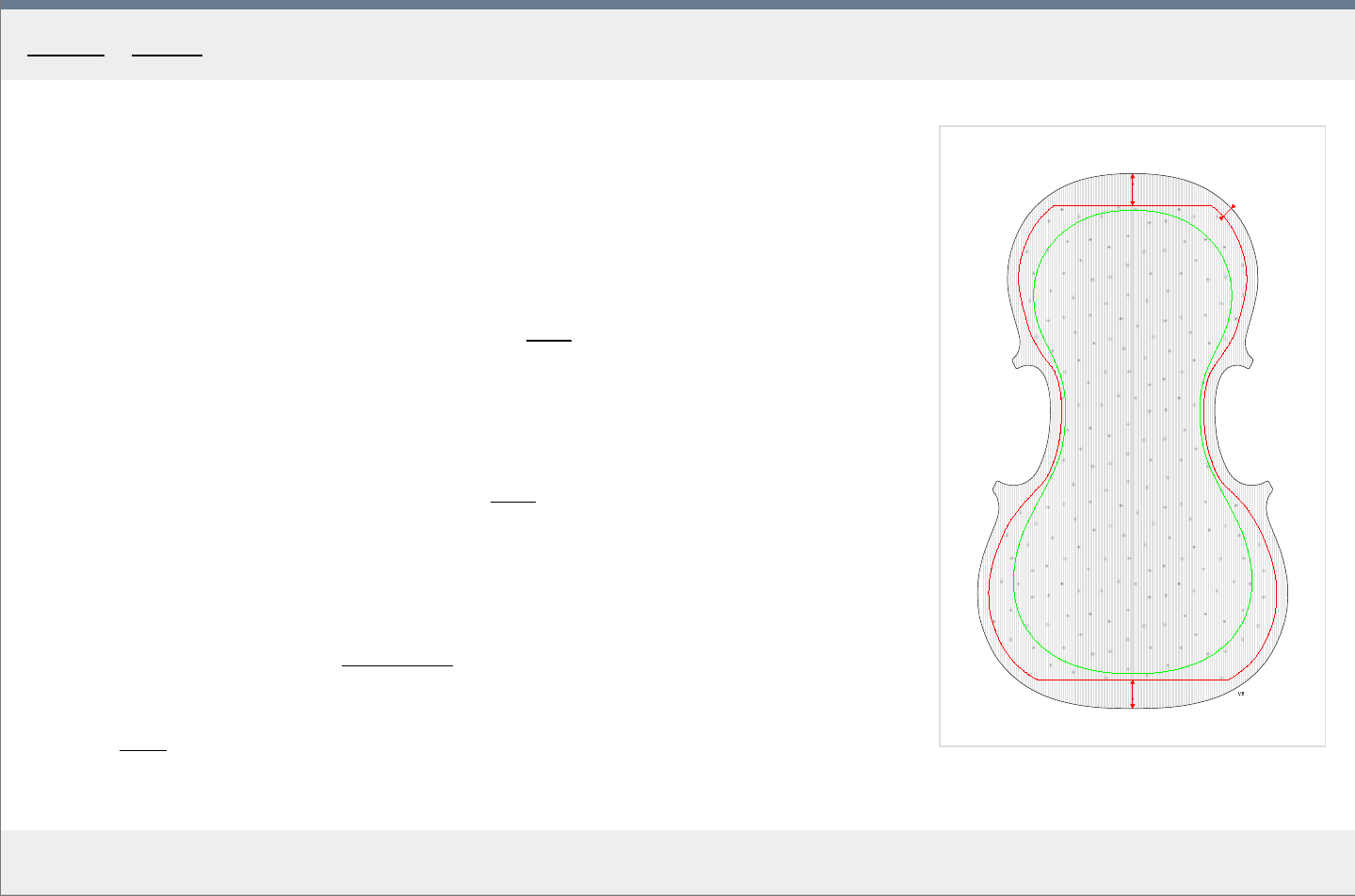
1
c
a
b
MakingTheViolin.com
Hollowing and thicknessing
1
. Mark out an outline on the bottom side of the plate, see the red outline in Fig. 1 . "a" is 21
mm , "b" is 19 mm , "c"
is 7 mm .
2. Mark a second green outline using a marking caliper set to a 5 mm thickness. This will
cr
eate a safety margin.
3. Mount the plate bottom up in the plate holder. See Tools
section for an example.
4. Start removing material within the green outline. Work across the grain. Keep checking the
thickness with a caliper or your fingers.
5. When you are getting closer to about 6 mm thickness, use a graduation punch set to 4
mm . For graduation punch schematics see the Tools
section of the site. Beware that this
only applies to the front plate. The back plate has different thicknesses.
6. Remove material all over the surface up to the red line, down to 4 mm , which means that
the holes fr
om the graduation punch will start disappearing.
Now you should move over to the Plate tuning
section to read up on how you might want to
tune the plate.
Category: Front
Home - F ront - Hollowing and thicknessing
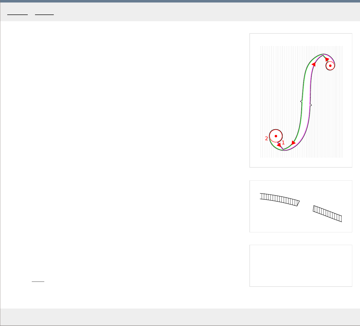
1
2
MakingTheViolin.com
Cutting the f -holes
1
. Mark the center of the four circles with a point.
2. Drill the four leading holes using a small, 2 mm drill bit at right angles to the ar
ching.
3. Use a f-hole cutter of suitable diameter to cut out the four holes. To make the cut as
smooth as possible, with each hole, start at top of the plate, cut half way, then continue
fr
om the bottom and make the finishing cuts again from the top. Make sure you are cutting
at right angles to the arching in place. Apply only moderate pressure to make a clean cut.
4. With the f-hole eyes cut out, use a coping saw, with a fine-toothed blade, to cut out the
r
est of the shape /the stem and the wings/. See Fig. 1. for the cutting order. Again, cut at
right angles to the arching. Start in the no. 1 position and end in no. 2 . It is good to lay
the plate down onto the fixed plank you used to cut out the plate outline before. This
allows for easy access and support while you rotate the plate as needed.
5
. Using a sharp pointy knife, start cutting the f-hole walls to their final dimensions. Always
work with the grain. Mak
e sure the broadest area at the notches is at least a little over 6
mm wide, so that the sound post /6 mm wide/ can be inserted through there.
The angle of the f-hole walls depicted in Fig. 2. is more or less the modern standard and it
can vary depending on the violin model. The gaps at the wing tips should have the width of
about 1 mm .
1
. Sharpen your knife extra sharp and finish both f-hole outlines to perfection because later,
you won't have the fr
ee access when the plate is glued to the ribs.
Cutting the notches
To cut the notches, first make a cut in the middle, then two cuts at angles to the first one. It is
always better to make the initial incisions small and work towards something bigger. The size
of the notches on the template in Fig. 1. can be considered ideal.
Category: Front
Home - F ront - Cutting the F -holes
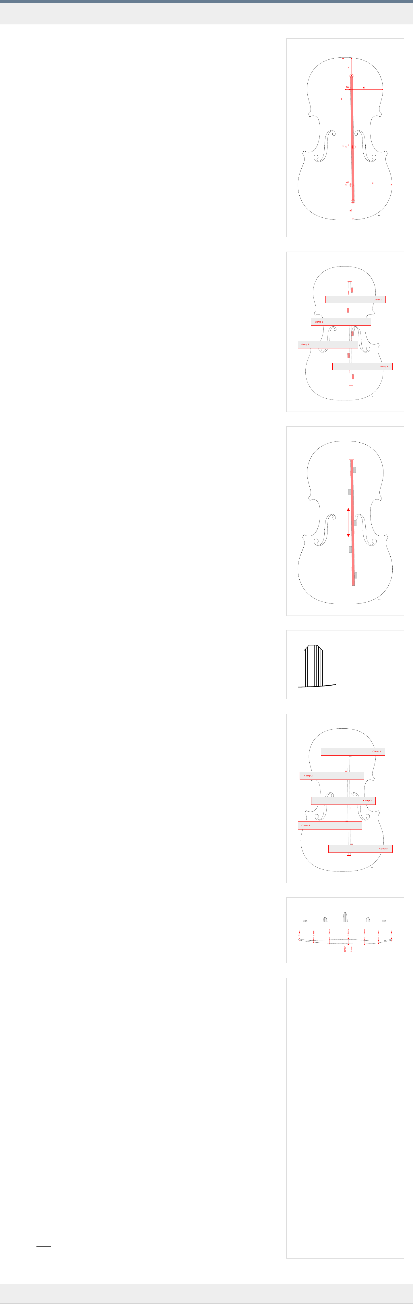
1
2
3
4
5
6
MakingTheViolin.com
The bass bar serves to prop up the arching as well as tune the plate and put it in balance.
The blank
1
. Split a piece of spruce 350 x 20 x 8 mm , ideally the same spruce you used for the top
plate.
2. Plane down the sides so that they run perfectly parallel to each other and the thickness if
the bar is about 6 mm for a flatter ar
ch or 5.5 mm for a higher arch and tighter grain. The
sides can be planed down to the desired thickness by putting the bar down on the
workbench and using a small C-clamp as a stop for it.
Positioning
A good position is crucial for both the sound and structural integrity. The bass bar runs right
under the bass foot of the bridge. Notice the slight tilt, causing the bar run a bit across the
grain, reinforcing the arch even more.
1
. Mark out the position of the bass bar on the plate, see the circles in Fig. 1 for wher
e to put
the marks. "a1" and "a2" are 40 mm , "b" is 196 mm , or precisely at the f-hole nicks
(bridge position), "c" is 19 mm . In our case, the half upper bout width is 84 mm , half
lower bout is 104 mm . To compute the "d" and "e" positions, the upper and lower bout
widths are divided by 7. Therefore 84/7=12 mm and 104/7=14.8 mm. The thick red line
shows where the bass bar will be eventually.
2
. Put the bass bar in position and trim its length so that it extends the "a1" and "a2 marks
at each end by about 5 mm .
3. Using your knife, trim the spots where the bass bar touches the plate to roughly fit it to the
ar
ching there. Make sure the center of the bass bar is not elevated more than 6 mm from
the plate on the left side as you will use a 6 mm washer to transfer the arching onto the
bass bar. Also make sure the bar is at right angle to the plane of the plate.
4. Spot glue the bar in those two spots. Check the position again. Wait 5 minutes for the glue
to set.
5. Using a washer that will offset the line by about 6 mm , draw a line copying the ar
ching on
both sides of the bass bar. When finished, break off the bass bar being careful not to
damage the surface of the plate.
6. Pare down the wood between the two lines using a knife, then perhaps a flat thumb plane
and a scraper until the bass bar fits quite well and most of all is at right angle to the plane
of the plate.
7. Lastly, if you use the wooden clamps, as in Fig. 2. , cr
eate a profile of the top of the bar as
in Fig. 4. to prevent the clamps from tilting the bar.
Studs
To hold the bass bar in position while being chalk fitted and glued, you need five wooden
studs. We put paper on the gluing side to make the later removal easier.
1
. Cut a piece of soft wood to 60 x 10 x 8 mm
and glue a strip of paper onto the 8 mm
(bottom) side. The grain orientation should be vertical, the same as the bass bar, to allow
for easier removal by splitting later on. Let dry.
2. Cut the five identical studs, about 10 mm wide, fr
om this piece of wood.
3. Use four wooden clamps or C-clamps as in Fig. 2 to clamp the bass bar in position. Mak
e
sure the bass bar is again perfectly vertical to the plane of the plate, when looking from
both ends. Also, check its overall position and make sure it stays within the marks, as in
Fig. 1 .
4. Start fitting the studs on alternate sides of the bass bar as in Fig. 2 . A well fitted stud sits
snugly against both the plate and the bar
.
5. With all studs fitting, start gluing them one by one, holding each in position with your
fingers for about 20 seconds. Mak
e sure the glue gets only on the paper bottom of the
stud, not the bass bar itself, avoid applying too much glue.
6. Wait 5 minutes for the glue to set, remove the clamps and carefully shuffle the bar a little
to ensur
e it didn't get stuck to the studs. Let dry for a few hours.
Chalk fitting
Chalk fitting helps you achieve the best joint between the bass bar and the plate.
1
. Remove the bass bar, take a piece of white chalk and rub it on the plate, where the bass
bar is supposed to be glued in.
2. Put the bass bar back in place and move it about 2 mm up and down, as in Fig. 3 a few
times to highlight the peaks to be r
emoved on the bass bar, moving it more than that
would lead to inaccurate imprinting. It is important not to put too much pressure on the
bass bar as the plate has a tendency to warp easily, resulting in inaccurate imprinting.
3. Use your thumb plane, scraper or knife (as a scraper) to remove the chalked peaks from
the bass bar
. Repeat, keep removing the peaks, reapply chalk, if needed, until the whole
bass bar fits well. The finest adjustments are again done best with your sharp knife used
as a scraper.
4. To remove the excess height of the bar to a necessary minimum, at the bridge position,
first mak
e a mark at the 15 mm height on the left wall of the bar. Then, extended that
mark, drawing a line up to the ends, making sure the height at those is not less than 7
mm .
5. Plane off the excessive height, keeping the top at right angles to the sides. This is best
done with a no
. 7 mounted in your vice upside down. If you need to, trim the studs so that
they stay below the top line (they snap off easily so be careful).
6. Again, if you use the wooden clamps, recreate the top profile as in Fig. 4.
Gluing
T
o clamp the bass bar for gluing, you can use the same clamps you used to hold the bar in
position for the studs, only 5 instead of 4 should be used. See Fig. 5 for the positions of the
clamps.
1
. Using your coarse brush, remove the chalk left on the plate.
2. Dry fit the bass bar again and try to put all five clamps on to see if everything fits well.
3. Prepare fresh medium hide glue, put some on the bass bar, insert the bar in place.
4. Quickly remove all excess glue with a coarse brush and clamp down as in Fig. 5 .
5. Let dry overnight.
T
rimming and shaping
Trimming and shaping integrates the bass bar into the plate finalizing its tuning.
1
. Pare away the studs with a knife or a chisel. Work from top down, along the vertical growth
lines cutting away thin slices. Be car
eful close to the bass bar as the stud may have been
glued to it. Moisten the remaining paper patches and remove them with a knife.
2. Plane the bass bar evenly so that at the bridge position it has the height of about 13 mm ,
measur
ed from the side close to the center line.
3. Refer to the bass bar diagram in Fig. 6. to see what the finished bar looks lik
e. The overall
shape depends much on the arching and plate tuning. Less stable arching, ie. low and or
with long straight central part, needs more support at the center. The bass bar brings the
M5 frequency back to where it was before the cutting out of the f-holes. The plate
becomes more rigid again so pay attention to that.
4
. During shaping keep measuring the M5 fr
equency and the weight of the plate.
5. When the general shape is achieved, the cross section as depicted in the upper half of Fig.
6. is to be worked out. Use first a thumb plane, then an abrasive paper. When fine-tuning
the bass bar bear in mind that just a few str
okes, especially at the ends, can lower the M5
considerably.
6. Trim the ends of the bass bar to the final length at an angle of 45 degrees as in Fig. 6.
The final length should not be mor
e than 7/9 of the plate length. So for a plate that is 360
mm long, the bass bar should be (7/9) * 360 = 280 mm or less.
Category: Front
Home - F ront - Bass bar
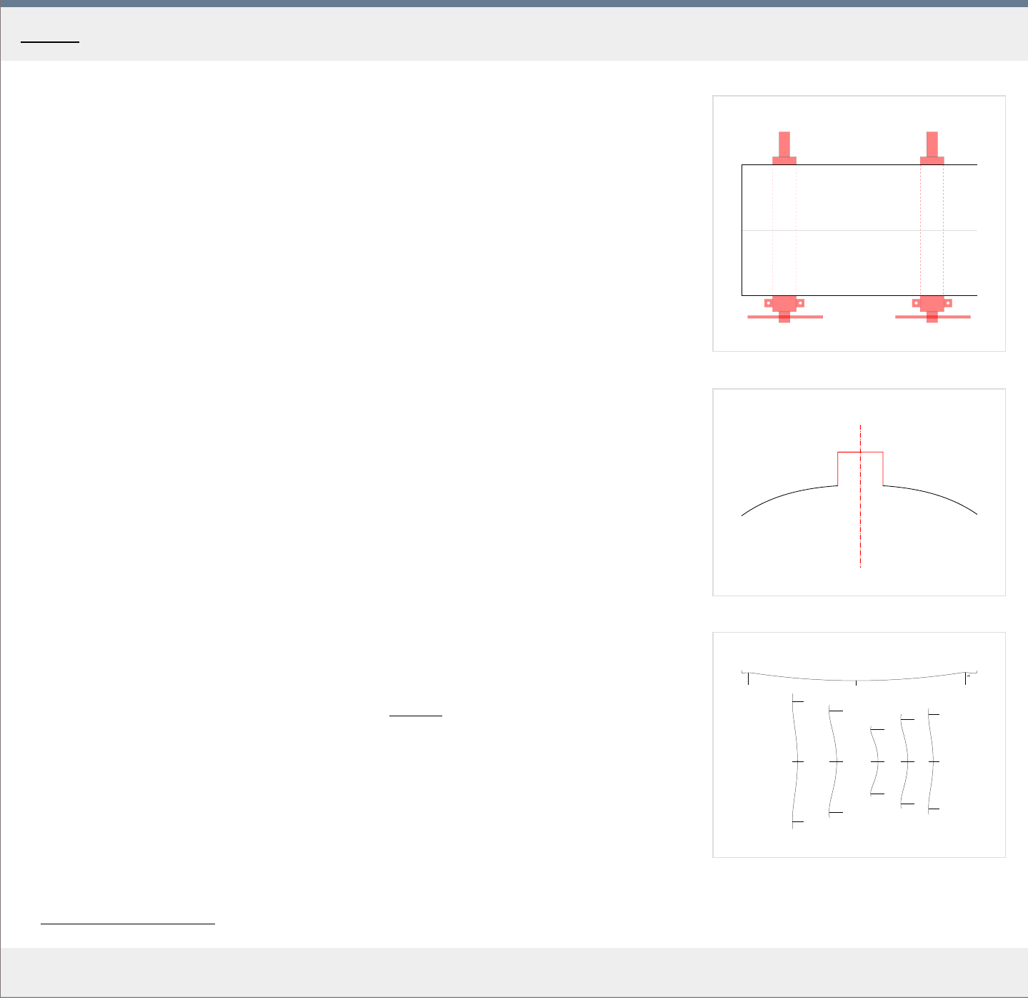
1
2
X
3
Back
MakingTheViolin.com
Almost all that applies to the front can be used when creating the back.
The wood is harder and carves differently. Bear in mind that deeply flamed wood is more
difficult to plane. To prevent tear-out, a razor sharp plane with the mouth set to a minimum
and the chipbreaker set very close are recommended. Also, for different parts, different
planing directions may be needed. For me a 9 1/2 block plane works best.
Also, check the density of the block and make a note of it for future reference. Go for lighter
wood {ideally maybe .55 density} which will allow you to end with a plate which has not
more than 110 gr of weight.
The joining of the two halves can be a rubbed joint as with the front, but it is more difficult to
make a perfect joint this way, so two sash clamps as in Fig. 1. are employed after the rub
joint has been carried out.
Button
The outline is identical, except for the place where the button will be. There, create a platform
22 mm wide and 15 mm tall. See Fig. 2. The final shape of the button will be finished later
when the neck root is in its correct position.
Purfling
The purfling for the back should be made of one piece for the top and bottom bouts.
Arching
The arching of the back may or may not differ from the front. In our case it is 16 mm high.
1
. Look again at the arching construction in chapter Arching
, Fig. 3 .
2. Print out the arching templates for the back in Fig. 3 . The template positions for the back
ar
e identical to those for the front.
Thicknessing
The thickness in the cheeks is often half the thickness in the center.
1
. Bring the thickness down to 6 mm at the center and 3 mm in the bouts, see the chapter
Graduations - back_plate
for an example of final thicknesses and their distribution.
Home - Back
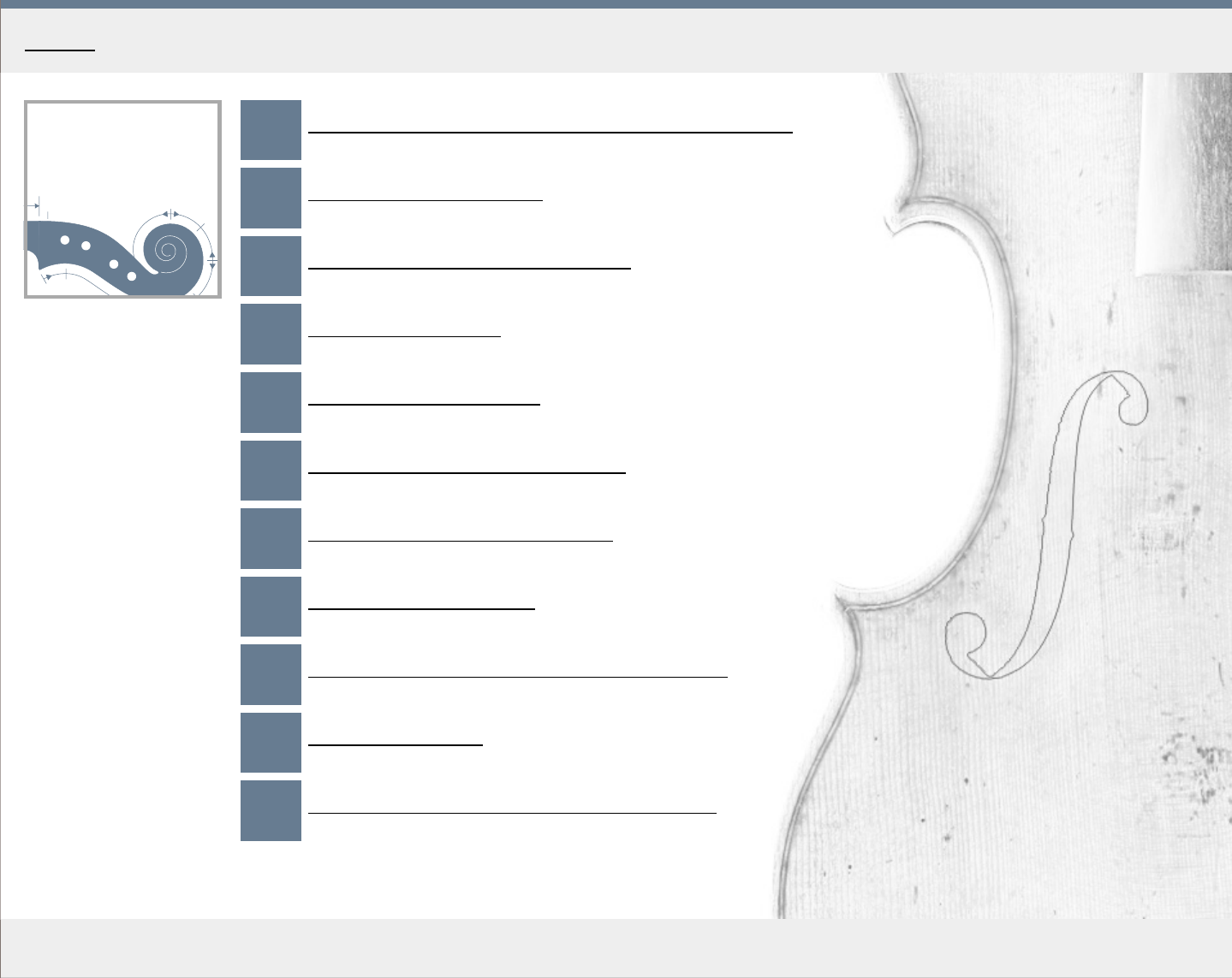
Neck and
scroll
MakingTheViolin.com
Home - Neck and scroll
1. Preparing the neck block and cutting the outline
2. Marking the neck blank
3. Cutting the sides and the volute
4. Cutting the pegbox
5. Chamfering and fluting
6. Preparing the fingerboard block
7. Shaping the fingerboard blank
8. Gluing the fingerboard
9. Shaping the neck root and adding the nut
10. Shaping the neck
11. Finishing the neck-scroll and fingerboard
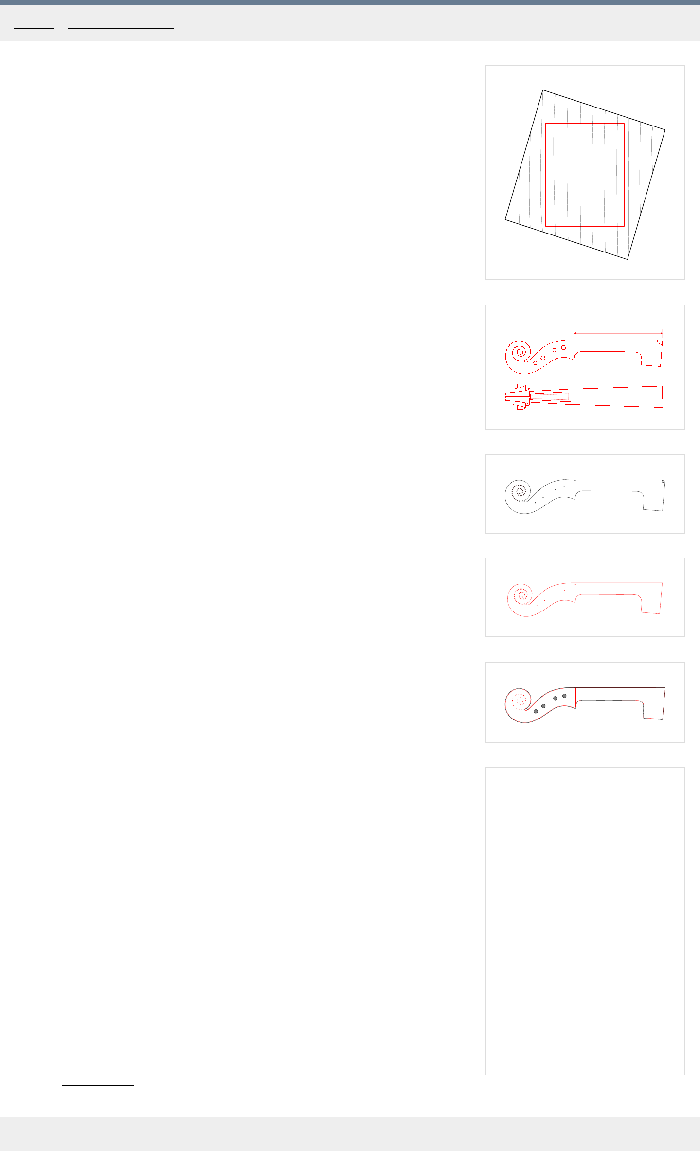
1
2
a
8 5
c
b
3
4
5
MakingTheViolin.com
Preparing the wood
1
. Choose a piece of maple, that matches in flame your back. The medullary rays should be
at right angles to the top plane, the gr
owth lines parallel with the top plane /fingerboard
gluing surface/. If you need to reorient the wood grain along the longest axis, you can use
a simple template 55 x 42 mm in size, made of plastic, as in Fig. 1.
2. True the block of wood to the minimal measurements of 250 x 42 x 55 mm . Check the
maximum width of the scr
oll you are copying, from eye to eye, and make sure it fits into
the 42 mm width of the block, the block being only about .5 mm wider.
Neck construction
In Fig. 2 you can see the general side and top overview of the finished neck and scroll. Note
the length of the fingerboard gluing area, which is 136 mm and the angle of the neck root at
85 degrees .
Neck template
For the neck template, you can use the same material as for the body template.
1
. Print out the template in Fig. 3 or use your own. The template her
e is again a slightly
corrected version of the Messiah neck and scroll.
2. Glue on and cut out in the same manner as the body template.
3. Drill the small holes using a 1 mm drill bit. They will allow you to mark the scr
oll, peg
holes and the end position of the fingerboard.
Marking the block
Use the neck template to transfer the neck outline on both sides of the block. Make sure the
top of the block is straight and without flaws as it will with no alterations serve as the gluing
surface for the fingerboard. For correct placement of the template see Fig. 4 .
1
. Clamp down the template in the correct position.
2. Using a pencil, mark the template outline as well as all the holes denoting the scroll, peg
holes and fingerboar
d end.
3. Repeat on the other side of the block. Make sure the template is in perfect alignment with
its pr
evious position on the other side.
4. Draw a line "c"
square to the top of the block, at the fingerboard's end position. See
Fig.2 .
5. If you have a drill press, you can now drill the four pegbox holes using a 6 mm drill bit. T
ry
this first on a block of scrap wood to see if you can drill precisely at right angle to the top
and bottom surface. Again a block precisely trued is necessary for this.
If you don't have access to a precise drill press or you for some reason must work with a
block of wood that is not perfectly squar
e, don't worry, you can drill the peg holes later by
hand.
Cutting the outline
1
. Use a coping saw or a belt saw to cut out the rough form of the neck. Avoid undercutting
constantly checking both outlines.
2. Remove excessive material with a knife close to the outlines on both sides. Then, remove
the wood inbetween using a gouge or a rasp or a file.
3. Using a sharp flat block plane and/or a file, make the back wall "b" , Fig. 2 , of the neck
r
oot flat. At the same time make sure the resulting fingerboard gluing area is precisely 136
mm and the neck root is at right angles to both sides of the block.
4. Size the neck root with thin hide glue.
See
Fig. 5 for the resulting neck block at this stage. The red line is the template, the black is
the actual cut out block.
Category: Neck and scroll
Home - Neck and scroll - Preparing the neck block
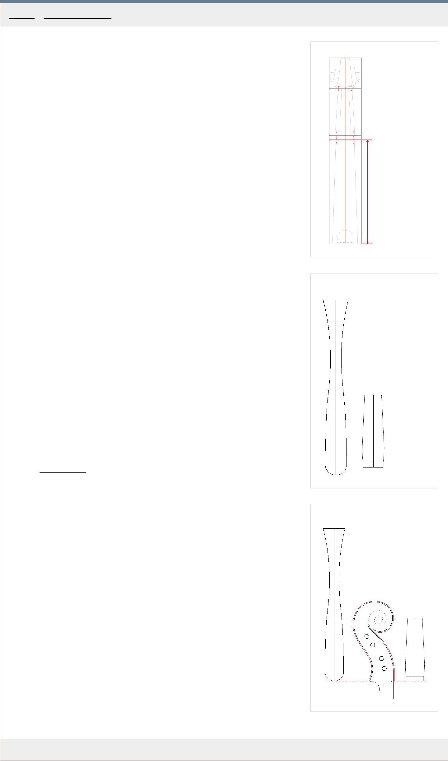
1
a
b
c
d
x
2
A
B
3
B
B
A
A
MakingTheViolin.com
Marking the top of the neck blank
While marking the top of the neck block, refer to Fig. 1 .
1
. Using a marking gauge make a centerline "a" on all four sides of the neck blank.
2. On the top side, at the distance "x" of 136 mm fr
om the heel, mark the line "b" which will
determine the end of the fingerboard.
3. Continuing from the previous line, mark another line "c"
, 6 mm forward in the direction of
the volute. This line determines the end of the nut and the beginning of the slopping wall
of the pegbox.
4. Set your compass to 12 mm and on each side, fr
om the centerline on lines "b, c" make a
mark which will denote the width of both the fingerboard end and the nut, in total 24 mm .
5. Use the same method, setting your compass to 10 mm , to mark the width of the begbo
x
at it lowermost side, line "d" , under the volute.
The scroll and pegbox template
Now it's time to create the scroll and pegbox templates. You can decide not to do the
cardboard templates which are good for reuse and instead go for the paper thin ones just to
quickly transfer the outlines. In that case, just print out the outlines in Fig. 2 , cut them out
using scissors and skip the following paragraph.
1
. Prepare two pieces of cca 1 mm thick car
dboard, one 220 x 40 mm for the "A" scroll
template and the other 100 x 40 mm for the "B" pegbox template.
2. Print out the outlines in Fig. 2 and glue them onto the r
espective cardboard pieces.
3. Cut out the outlines as precisely as possible.
4. Wet the paper and impregnate it with thin hide glue. Remove the excess of hide glue. Let
set for and hour
.
5. Put the templates in their correct positions, shape them around on the neck blank and
clamp lightly in position so that they don't get stuck to the wood.
6. Let dry.
Marking the outlines
1. Correctly align the paper templates. See Fig. 3 wher
e the starting point for both templates
is at the heel and fingerboard end {red dashed line}.
2. Using a pencil, mark the outlines of both the pegbox and the volute on the neck blank.
Category
: Neck and scroll
Home - Neck and scroll - Marking the neck blank
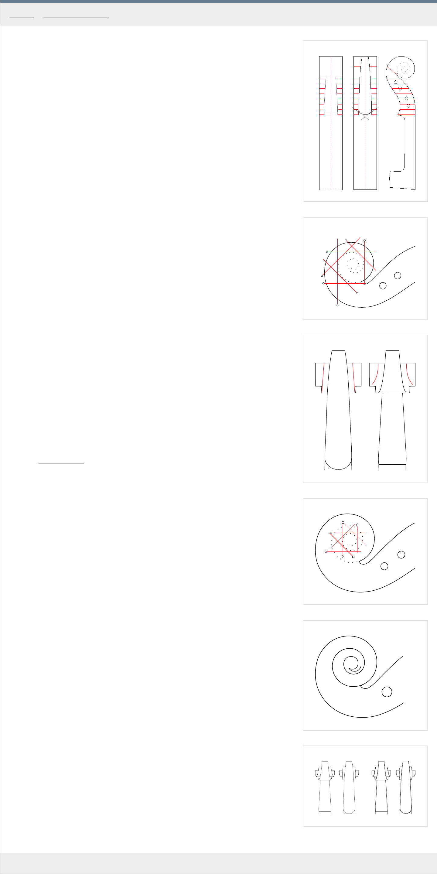
1
f
c
2
1
2
3
4
7
5
6
3
4
1
2
3
4
7
5
6
5
6
MakingTheViolin.com
First of all, it is great to have a good finished neck at hand for reference. If you do not have it,
study the photographs of the neck you are copying.
Cutting the sides of the peg box
1
. From the fingerboard end line "f" in the dir
ection of the volute, start making incisions
using your saw, about 1 cm apart, stopping 1 mm short of the marked template lines. End
in the area of the throat. See Fig. 1 for more information.
2. The little blocks of wood can now be removed with a chisel. Be careful to read the wood
grain, do not try to chip away the whole block, work gradually in slices and from both
sides.
3. Saw off the little pieces forming the basic contour of the heel. To avoid undercutting, angle
the saw slightly away fr
om the heel. See the "c" cuts in Fig. 1 .
4. Using a flat rasp/file, reduce further the width of the pegbox up to the lines, make the heel
r
ound.
Cutting the volute
Look at the Fig. 2 and Fig. 3 to see the way in which the volute will be cut. The red lines
denote incisions. The order of the cuts is not important but it makes sense to proceed as
numbered. Always stop a mm from the template lines.
1
. Make the incisions no. 1-6 along the lines as in Fig. 1 and r
emove the resulting pieces of
wood using a small shallow gouge.
Notice that incision no. 7 has no boundary line at one end, as the template ends ther
e.
2. To make the cut no. 7 and to pr
oceed on to the second set of incisions as depicted in Fig.
4, you need to draw a line in the middle of the volute, as in Fig. 3 /the red lines/, naturally
extending the template lines.
3. Make the cuts down to the lines as in Fig. 4 and r
emove the resulting pieces of wood
using a small shallow gouge.
4. Now the final part of the volute, leading to the eye, remains to be carved. Start creating
the slope fr
om the tip of the eye using a suitable gouge. See Fig. 5 .
5. Correct the volute so that it flows naturally and gracefully.
6. Using a file, create a bevel on both edges of the volute and the heel.
7. Use small gouges to give the volute an increasing depth, as it approaches the eye.
See the finished scr
oll in Fig. 6 .
Category: Neck and scroll
Home - Neck and scroll - Cutting the volute
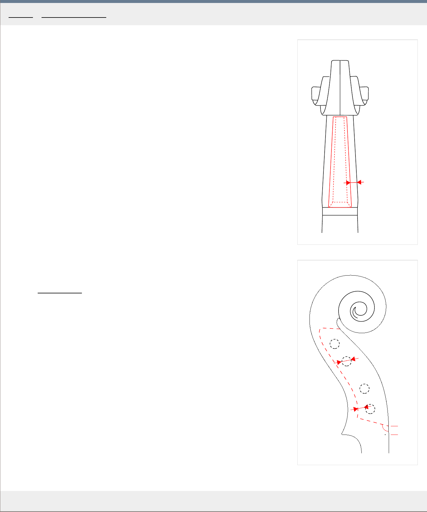
1
t
2
b
c
a
t
x
r
MakingTheViolin.com
Drilling the peg holes
1
. In case you have not predrilled the pegholes, realign the neck template and remark the
four peg holes with a scribe (needle). Check the positions of the marks and make
cor
rections where necessary.
2. Drill the four 6 mm wide "r"
holes starting first on one side, drilling half way. When the four
holes are half drilled, drill them from the other side. Do not drill more than half the length
on each side.
A good technique is to clamp a hand (of power) drill in your vice and hold the pegbox in our
other hand. Drill slowly constantly checking on the position of the drill bit.
Carving the peg box
1. Mark the extent of the pegbox by drawing parallel lines to the pegbox walls inset by 5 mm ,
"t" , as in Fig. 1.
Note that the walls ar
e getting thicker towards the floor of the pegbox, see the dashed red
line. The front wall, forming the extension of the nut "b" , runs at an angle of approximately
105 degrees , "x" in Fig. 2 . The bottom of the pegbox should be of consistent thickness at
the same time allowing sufficient space for the strings, placing it normally about 4 mm ,
"t" , below the pegs, see dashed line defining the bottom in Fig. 2.
2
. Start removing wood using a suitable (preferably U shaped) gouge. Make sure you are not
r
emoving too much wood - the pegbox sidewalls should not be thinner than 5 mm at the
top and 7 mm at the floor.
Category: Neck and scroll
Home - Neck and scroll - Cutting the pegbox
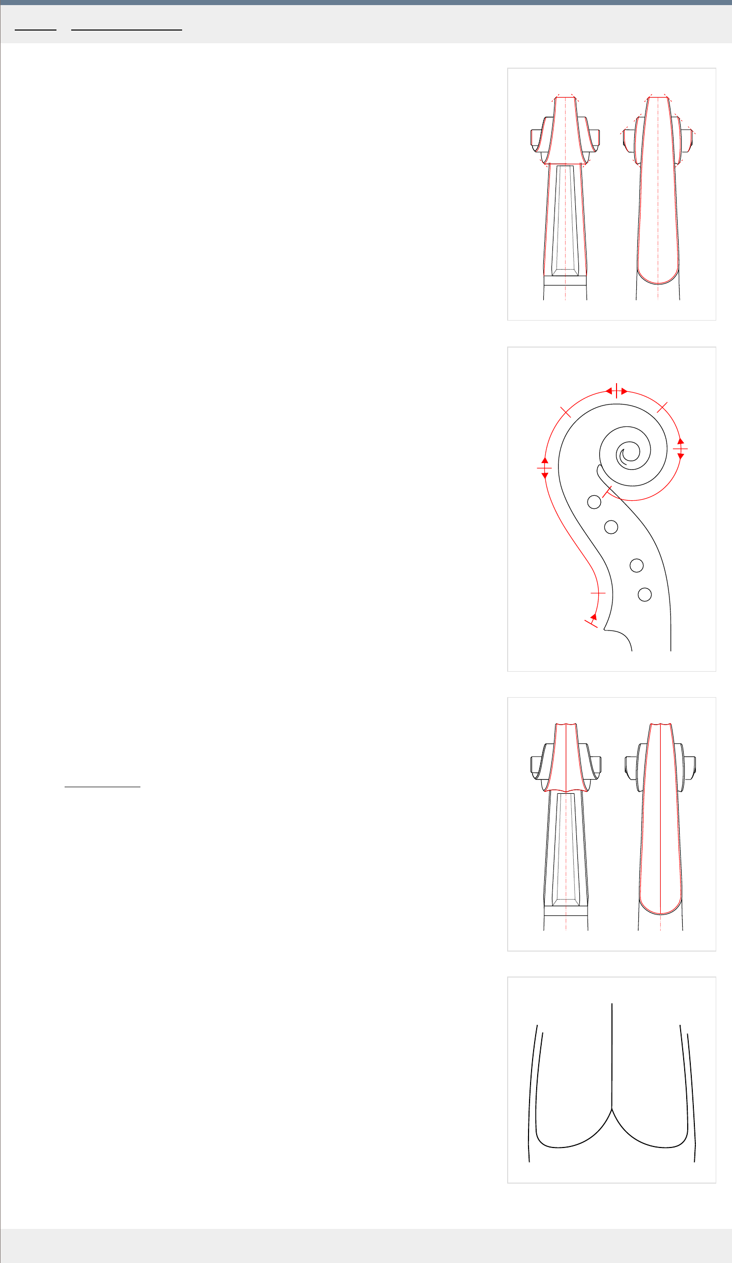
1
2
a
b
c
d
e
f
g
3
4
MakingTheViolin.com
Chamfering the scroll edges
With the general shape of the pegbox and scroll finished it is now time to chamfer the edges.
1
. Check again the scroll and pegbox for errors.
2. If all flows naturally, chamfer the edges as in Fig. 1 using a file. The r
ed dashed lines
denote the angle of the file.
The fluting
Before the the fluting is carved, make sure again that the general outline is flawless. At this
point, it is great to have a variety of gouges to choose for different shapes of the fluting. The
gouges should have the edges ground in a round shape, like the bottom of the letter U. Again,
it is great to have a finished neck at hand for reference.
1
. If necessary remark the center-line from the heel to the end of the volute.
Look at Fig. 2 to see the dir
ections you should follow when cutting the fluting. These
should make the cutting easiest and most efficient with regard to wood grain.
2. Start at point "a" with a small no
. 7 gouge and go down the slope, right next to the
chamfer.
3. When the spade widens make another cut right next to the first one, this time getting
close to the centerline.
4. Using a wider, shallower gouge, unite the two paths.
5. Continue in the opposite direction from the heel, point "b" , and connect to the "a" path.
While cutting the "b" path, right at the heel, consult Fig. 3 for how the shape of the fluting
looks at the heel.
6. Continue with the "c"
path and connect the "d" , starting at the top of the scroll, to it. At
points "d and e" it cuts slightly differently as the grain orientation is at right angle to the
cuts. Use a small gouge with an edge fitting the fluting groove here.
7. Start the "f" path and connect it to the "e"
path. At "f" the path is again wide enough for
two cuts.
8. The "g" path ends just above the peg bo
x. See Fig. 4 for the shape of the ending.
9. Repeat all steps on the opposite side of the centerline.
10. Use scrapers to finish the fluting. Again, follow the grain as when you were cutting.
11. Redo the chamfer where necessary making sure the outline of the scroll when viewed from
all angles r
emains natural.
Category: Neck and scroll
Home - Neck and scroll - Fluting
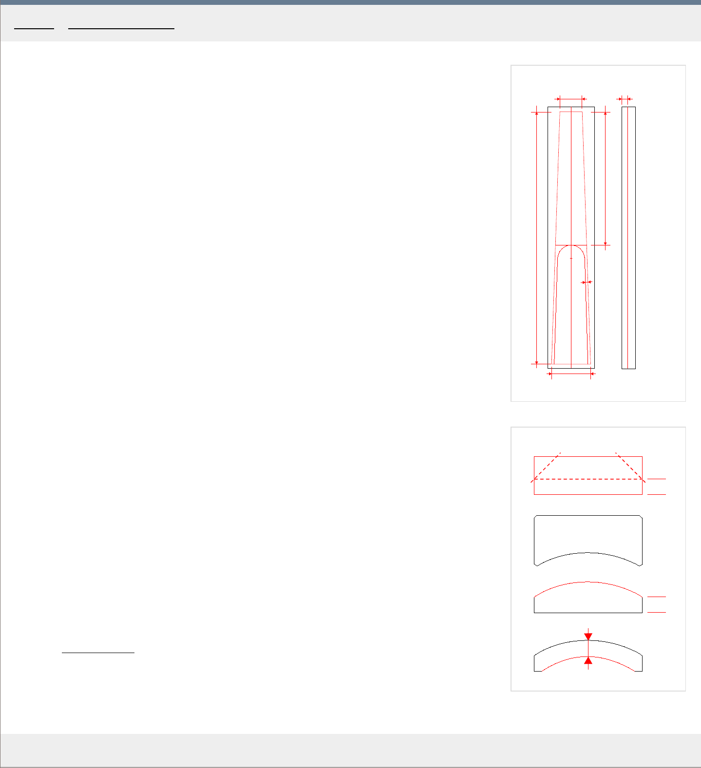
1
c
o
d
t
w1
w2
l
ha
x
h
2
Template
h
t
h
MakingTheViolin.com
Preparing the fingerboard block
This method can be used, when you want to create you fingerboard from scratch. When using a
premade fingerboard blank, you can skip this section.
1
. True a suitable block of ebony to get a piece that is approximately 280 x 50 x 15 mm .
2. Make a centerline "c"
on the bottom of the block. See Fig. 1.
3. Now you need to mark out the outline of the fingerboard "o" . Alter
natively, take a suitable
fingerboard blank, align with the block and mark its outline with a scribe. Highlight the lines
with chalk.
4. At point "x" use a compass to mark the upper ar
c of the hollow area "h" , starting at the
distance "d" from the top end of the fingerboard, which is 142 mm . Allow "t" 3 mm for the
sides. Again, highlight with chalk.
5. Saw off the sides, staying about 1 mm outside the lines.
6. Plane the sides down to the lines making sure the top 24 mm and bottom 42 mm widths ar
e
met and that both sides are perpendicular to the bottom.
7. Using a block plane, create a small concavity along the length of each side of max. 1 mm at the
center of the fingerboar
d. Check with steel ruler.
8. Make a line on both sidewalls with the height "h"
of 6 mm from the bottom, apply chalk. See
the side view of the fingerboard in Fig. 1. Use a block plane and plane down the edges to the
lines on both sides, see Fig. 2.
9. Make a template as in Fig. 2. Use that template to achieve the radius with the height "h"
of 6
mm at the sides, throughout the length of the fingerboard.
10. Now is the time to carve out the hollow area "ha" as in Fig. 1. The thickness "t" , e
xcept in the
area of the arch should be about 6 mm , see Fig. 2.
11. Trim the length of the fingerboard blank to 271 mm .
12. Make sure the top /24 mm/ and bottom /42 mm/ widths still apply. If not, remove more material
fr
om the sides.
You have got your fingerboard blank.
Category: Neck and scroll
Home - Neck and scroll - Preparing the fingerboard block
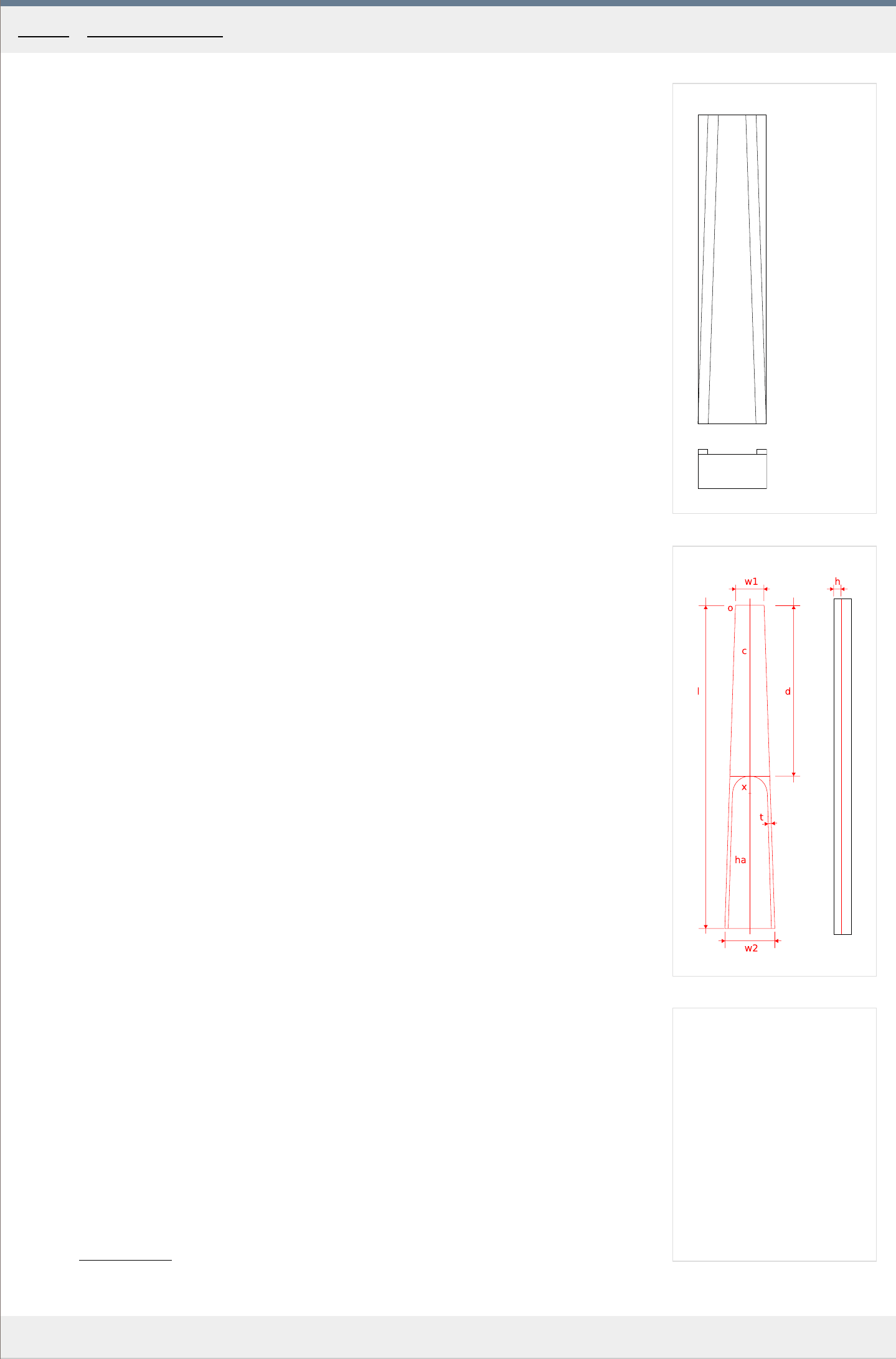
1
2
MakingTheViolin.com
Making the fingerboard holder
1
. Prepare a precise block of hardwood measuring 270 x 60 x 30 mm , see Fig. 1. for its simple
construction.
2. Make two strips of hardwood measuring 5 x 9 x 270 mm
.
3. Get a fingerboard blank, put it on top of the block
4. Glue on each side of the blank the two strips.
5. Clamp down the strips.
6. Remove the blank.
7. Carve out the material between the strips according to the top radius of the fingerboard blank, see
the bottom of Fig. 1. for the finished holder's wider end pr
ofile.
Shaping the fingerboard blank
Ebony is both very hard and prone to chipping.
1
. Place the fingerboard blank into the holder and clamp the holder in the vice.
2. Plane the whole underside of the fingerboard down so that the sides are about 5 mm thick.
3. At the bottom, mark the w1 24 mm and w2 42 mm widths and cr
eate lines from these marks
using your scribe. The lines may be made more visible by the application of white chalk.
4. Plane the sides down to the lines making sure that both sides stay at right angles to the bottom. If
necessary r
eadjust the height to 5.5 mm .
5. Remove the thickness on the underside of the fingerboard, gradually, starting at the 139th mm ,
r
emoving about 0.5 mm at the very end of the fingerboard, see the dashed line in fig. This way,
because the top of the fingerboard will later be planed a little concave as well, the final thickness
of the sides of 4.5 mm can be retained.
6. You may now, using a block plane, create a small concavity along the length of each side of max. 1
mm at the center of the fingerboar
d. Check with steel ruler.
7. Mark the hollow area ha , starting d 142 mm /6 mm fr
om the neck root/ from the top end of the
fingerboard, allowing t 3 mm for the sides. Use your compass at point x to create the arch, trace
with a needle. Highlight with chalk.
8. Remove some material with a gouge, getting down to about 5.5 mm thickness, fr
om point x up to
the end. The final thicknessing is done with the fingerboard glued on the neck.
9. Mark a height line h
of 4.5 mm on both sides of the fingerboard. That will be the final height of the
fingerboard sides. Highlight with chalk.
10. Last, check whether the new underside of the fingerboard sits perfectly on the top of the neck.
Sometimes the neck may twist a little as it dries and that must be corr
ected /plane/.
Trimming the fingerboard's ends
If you started with a premade fingerboard blank, which was already cut to the correct length of 270
mm and those cuts are clean, you can skip this chapter altogether.
1
. Inspect the ends and decide which end to cut, if just one or both. Mark the corr
ect length I of 270
mm .
2. Cut with your fine-toothed saw. Be extremely careful to prevent chipping.
3. Finish with sandpaper on a block of wood and/or a file. Make sure the new ends are at right angles
to the underside.
Category
: Neck and scroll
Home - Neck and scroll - Shaping the fingerboard blank
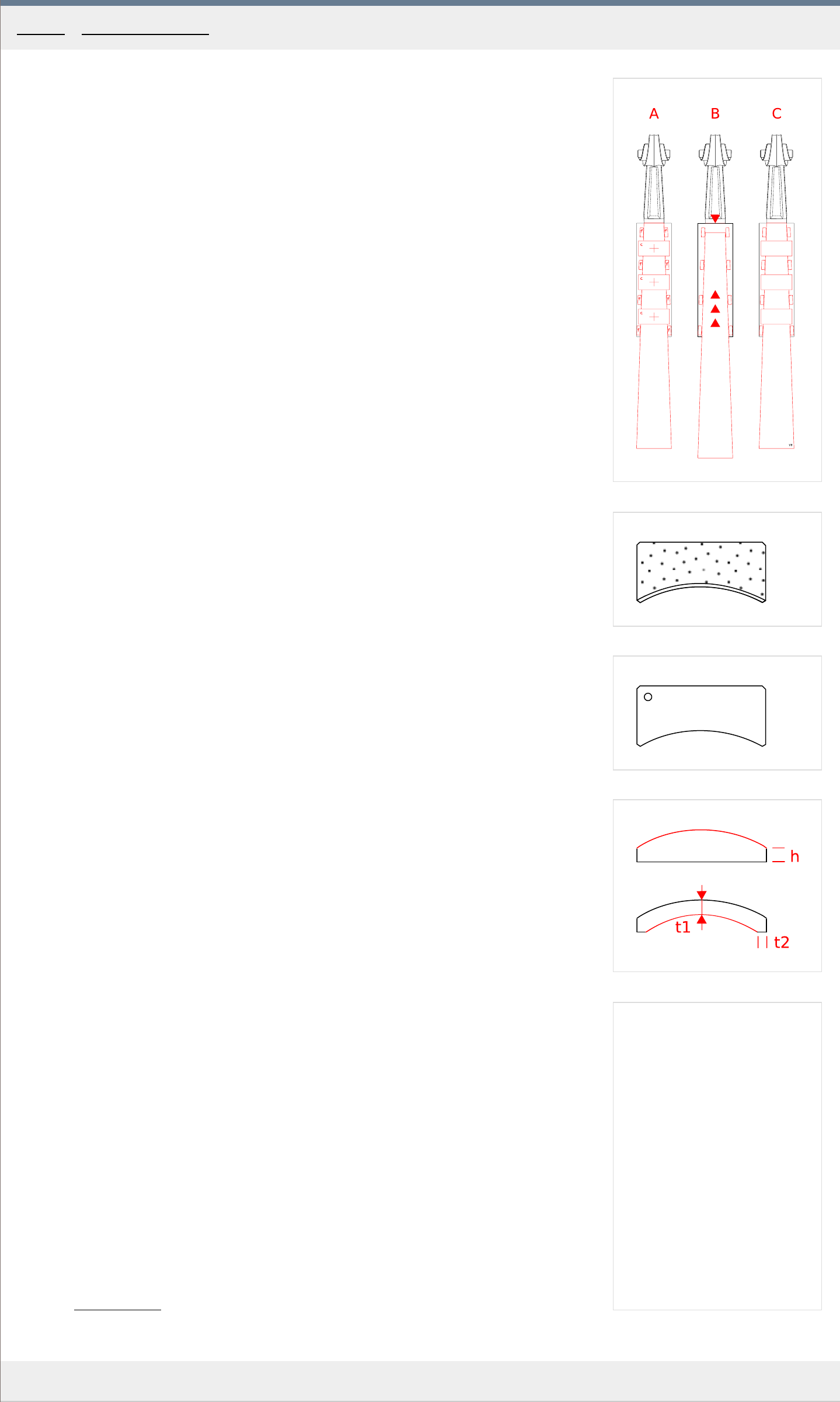
1
2
3
4
MakingTheViolin.com
The clamping blocks
To hold the fingerboard in position with the help of C-clamps, you need three clamping blocks. You
can see the the cross-section of such a block in Fig. 2 . The size is 40 x 30 x 25 mm . They are
made of hard wood, their bottoms padded with something soft, ie. cork or rubber. They go between
the C-clamp and the board, see neck C in Fig. 1 for their position.
Adding fingerboard fixing blocks
The fixing blocks help hold the fingerboard in the correct position during gluing. Consult Fig. 1 as
to the fingerboard, fixing blocks and clamps placement.
1
. Create 8 blocks of maple, 10 x 5 x 5 mm
in size.
2. Fix the neck in the vice and clamp down the fingerboard using three C-clamps and the clamping
blocks, in the cor
rect position. See "A" in Fig. 1 .
3. Adjust the blocks so they fit perfectly at the same time not conflicting with the projected
position of the thr
ee clamps.
4. Glue the fixing blocks onto the maple neck, holding each one for about 30 seconds. Again see
"A" in Fig. 1. for their appr
oximate positions.
5. Let dry for a few minutes and then carefully slide out the fingerboard to prevent it getting glued
to the blocks.
6. Let dry thoroughly.
Gluing the fingerboard
1. Reinsert the fingerboard between the fixing blocks and make sure it slides right up the marked
r
ed line, 6 mm before the sloping pegbox wall. See "B" in Fig. 1 .
2. Prepare thin hide glue, quickly apply to the underside of the fingerboard and slide in position.
The move must be a pr
ecise one as there is usually little time for correction before the glue
"bites". It is handy to have a small hammer at hand so that if the fingerboard "bites" short of
the marked line, you can tap it at the end lightly to get it home.
3. Apply three clamps with padded clamping blocks, see "C" in Fig. 1 for their positions. Use
moderate for
ce to tighten them. Make sure the fingerboard remains in the correct position.
4. The 8 maple fixing blocks can be r
emoved either after 10-20 minutes , provided you don't
remove the clamps, or when completely dry, at which time you must be careful not to chip away
the ebony fingerboard, removing the blocks in layers, gradually with a chisel.
5. Let dry overnight.
Finishing the fingerboard
T
o check the fingerboard radius, you need to make the radius template as in Fig. 3 .
1
. On both sides, use your block plane to reduce the height "h"
, Fig. 4 , of the fingerboard to the
marked line of 4.5 mm .
2. Continue removing wood from the top as well, occasionally checking the arching with the radius
template.
3. When you are getting closer to the final heights, try to create a slightly concave surface, with 1
mm at the G side and 0.75 mm at the E
side at the center of the fingerboard.
4. Finish with your scraper.
Hollowing out the bottom side
1. Insert your neck fingerboard-down into the fingerboard holder and clamp the holder in the vice.
2. Using a suitable gouge, start working across the grain, within the limits of the marked out area.
The final thickness "t1" starting at about 30 mm down fr
om the neck root up to the end of the
fingerboard should be 4 mm . The width of the edge "t2" is 3 mm .
1. Finish with your scraper.
Category
: Neck and scroll
Home - Neck and scroll - Gluing the fingerboard
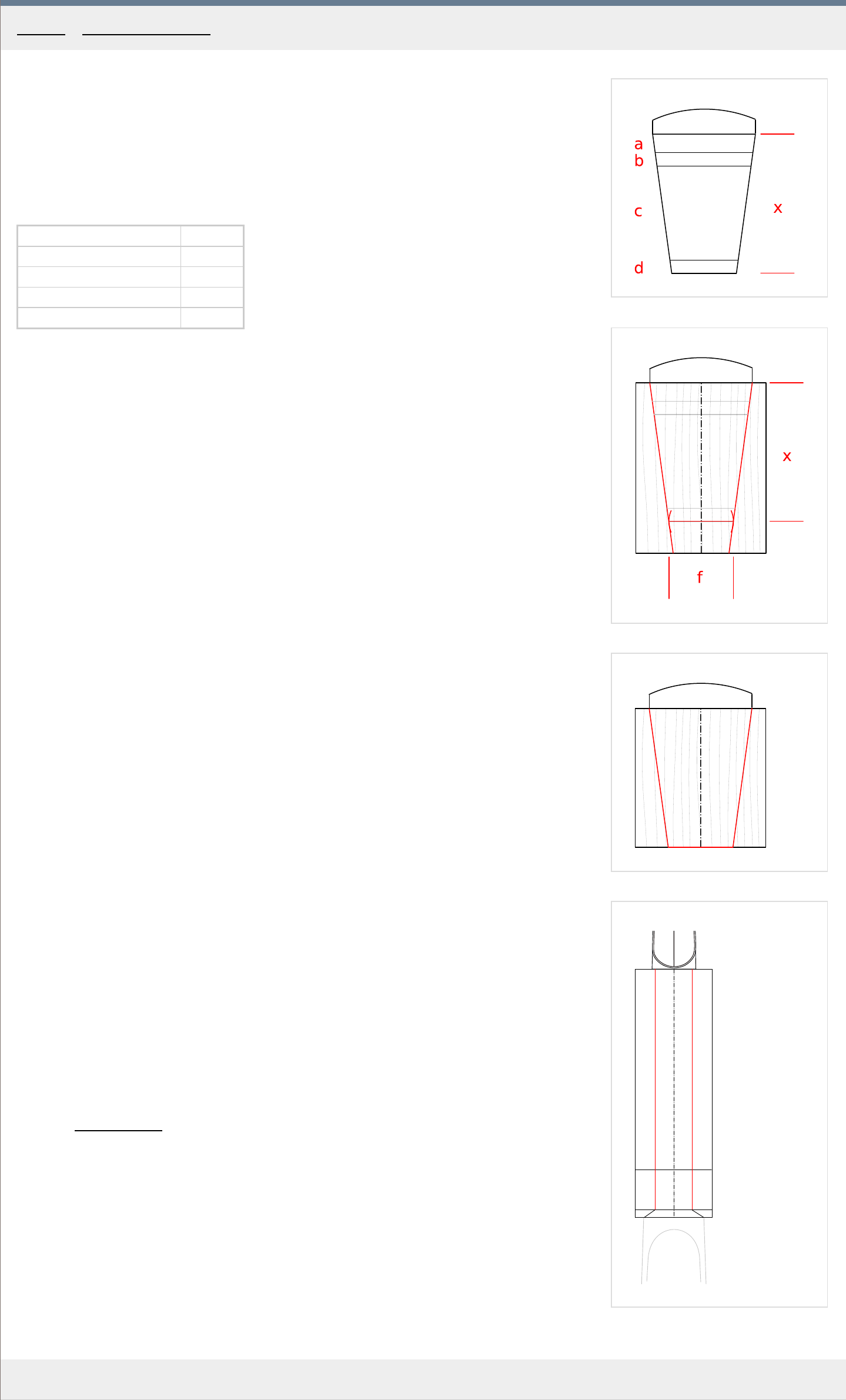
1
2
3
4
MakingTheViolin.com
Marking the neck root
First, you need to calculate the final height of the neck root. To do that, you need to measure the
height of the whole violin body /ribs+top+bottom plates/ where the neck root is inserted. The
measurements are taken from the violin you are copying.
It is helpful to create a table summing up the measurements. See Fig. 1. for an illustration of a
finished neck root. For our violin the numbers are as follows:
Overstand "a" 6.5 mm
Top plate thickness "b" 4.0 mm
Rib height "c" 30 mm
Bottom plate thickness "d" 4.0 mm
Total "x" 44.5 mm
Take a look at Fig. 2. First, you will need to mark the red lines.
1
. Mark the total height "x" , starting fr
om the fingerboard underside down the neck root wall,
using a scribe.
2. On this line, use a compass to mark, from the centerline, the width "f" of the button +0.5 mm .
The button width for the Messiah is 17.5 mm plus 0.5 mm , 18 mm in total.
3. Using your steel ruler mark the sides of the neck root wall. See the red lines marking the walls
in Fig. 2.
4. Trim the height of the neck root to the bottom line, retaining the angle, as in Fig. 3.
5. Extend the side marking lines to the bottom side of the neck root as well as to the neck's
underside. See Fig. 4 for r
eference.
Adding the nut
1. Clean the nut bed of any remnants of glue.
2. To create the nut blank, get a block of ebony and cut it to the dimensions of 8 x 7 x 26 mm
.
The grain direction should be that of the fingerboard.
3. True the back and bottom sides, which will be glued to the fingerboard and neck so that they
ar
e at right angles and the nut sits well in its projected gluing position.
4. Using your block plane and a file, create the front wall, sloping flush with the pegbox wall.
5. Put the nut in place and trace the radius of the fingerboard, including the sides, on the back
wall of the nut.
6. Trim the width of the nut so that it stays only a little proud of the fingerboard width. Be careful
when sawing off the ends as they easily split.
7. Using your knife, trim the nut above the line of the traced radius, but stay 1 mm above it.
F
inish roughly with your file.
8. Glue the nut with thin hide glue and holding in place with your hands for about 30 seconds .
9. Remove excess glue and let dry.
10. After the glue has dried, you may reduce the width of the nut further, so that it extends only
fractionally beyond the width of the fingerboar
d.
The nut will be finished later after we have shaped the rest of the neck.
Category: Neck and scroll
Home - Neck and scroll - Shaping the neck root

1
2
3
4
MakingTheViolin.com
Shaping the root and the sides of the neck
1
. Using your saw, start making incisions at both sides of the neck, about 1 cm apart,
starting with the neck r
oot on up to the heel. Make sure you stop 1 mm short both of the
fingerboard and the line on the underside. See Fig. 1. for reference.
2. With a chisel chop off the resulting blocks of wood, working away from the fingerboard. To
k
eep the splitting under control, work gradually, removing slices rather than whole blocks.
3. Finish the 10 mm wide part "a" in Fig. 2. , adjacent to the fingerboar
d, with a file. The file
should be slightly angled away from the fingerboard. Be careful not to cut into the
fingerboard too much. Create a surface that flows smoothly into the fingerboard sides. See
Fig. 2. for the enlarged cross section of the finished neck.
4. Using a block plane, finish the sides of the neck root up to the scribed lines. Be careful not
to dent the fingerboar
d edges extending beyond the root.
Shaping the neck
1. First, take a look at Fig. 3. , namely the neck "A" . Scribe two marks "a" and "b" on each
side of the neck, at the distance of 25 mm fr
om the nut and 50 mm from the neck root.
2. On both sides, mark the thicknesses "c"
19 mm and "d" 21 mm /18.5 and 20.5 being the
final thicknesses on the finished neck/ in these areas, measured including the fingerboard.
3. Connect these with a straight line "f" on both sides.
4. Measure 110 mm fr
om the heel towards the neck root and make a mark "e" , which will
serve to position the template.
5. If you haven't already, create a neck template as you have your other templates before.
Again, you can print out the template in Fig. 3. , glue it to the templating material and
transfer the outline this way
.
6. Using this template, transfer the contour marked "root" so that it is aligned with the mark
on the neck r
oot. Use the "chin" end of the template to transfer the contour of the heel on
the unfinished heel. Repeat on the other side.
7. Take look at neck "B"
in Fig. 3. . Make incisions 1 cm apart ending 1 mm clear of the two
dashed lines you just created.
8. Chop off the wood blocks in the same manner as you did on the sides of the neck.
9. Along the length of the underside of the neck, scribe a parallel line at about 1/3 distance
fr
om the fingerboard, see Fig. 4. The same on the other side.
10. Between these two lines the wood can be safely removed using a rasp. It may be difficult
to clamp the neck in the vice for this, so try opening the vice just enough to lay one side
and part of the top of the fingerboar
d on the vice. Hold with your hand and file away.
11. Level the underside of the neck and get to the final numbers, check with the template
of
ten. With a rasp make the coarse outline of the neck.
12. Using a file, start getting closer to the final curvature of the neck, check often with the
template
"g" and "h" at the points "c" and "d" . Keep checking the thicknesses in these
points too. When the template almost fits, you should be close to the numbers "c" 19 mm
and "d" 21 mm .
13. Using your knife, create the shape of the nape, make sure its contour flows smoothly into
the pegbo
x sidewalls.
14. Using your knife, roughly form the round shape of the heel. The final shaping is done later
with the neck glued on.
The final shaping of the neck is done later with the neck glued on.
15. Trim the ends of the nut so that they are flush with the finished surfaces. They should form
a smooth transition fr
om the sides of the fingerboard, usually widening a little to
accommodate the peg box walls. Finish with fine file.
Category: Neck and scroll
Home - Neck and scroll - Shaping the neck
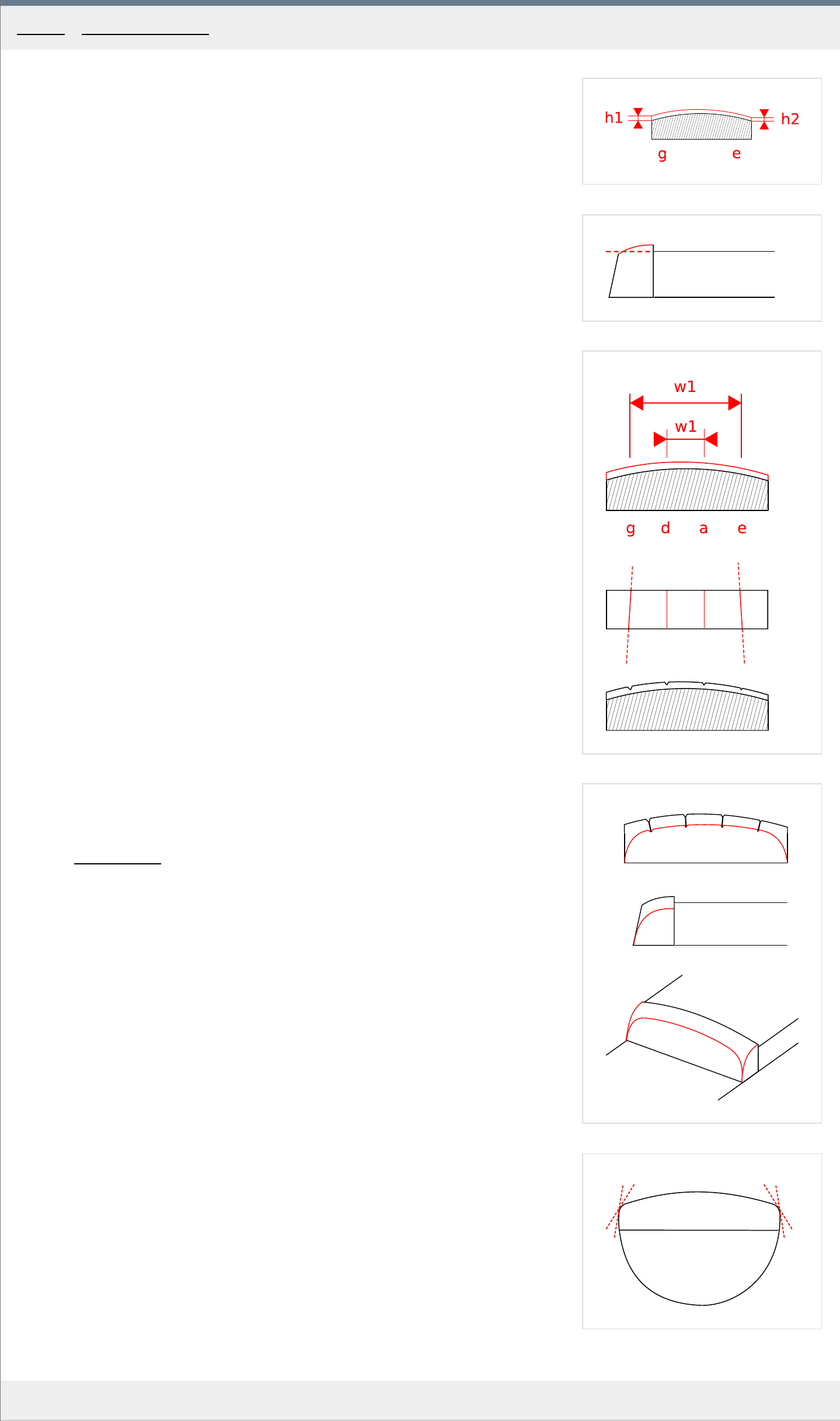
1
2
3
4
5
MakingTheViolin.com
Finishing the nut
1
. Take a look at Fig. 1. Using a file, finalize the ar
ching contour of the nut to 1 mm at h1 on
the G side and 0.75 mm at h2 on the E side.
2. Take a look at Fig. 2. which depicts the sloping of the top ar
ch. The slope goes towards
the pegbox and ends a little under the projected top of the fingerboard (see the red
dashed line). The slope can be created by using a file moving in short strokes in the
direction of the scroll, slightly angled. The angle of the file can be set by putting your
finger underneath the handle, the finger serving as a wedge, sliding on the fingerboard.
3. Finish the arching with fine sandpaper.
4. Set your compass to 16.5 mm , w1 in Fig. 3.
and at the top of the nut, mark the outter
positions for the G and E strings, leaning a little to the G side so that the E string will have
a little more space on the fingerboard.
5. Set your compass to 5.5 mm (
w2 ) and repeat to mark the inner positions for the D and A
strings.
6. Use a knife to cut through these marks, creating guides for a keyhole file. The guides for D
and A strings ar
e straight, those for G and E are cut at a slight angle, see Fig. 3.
Using a four-sided keyhole file, create the final grooves for the strings. Do not make them
too deep as the string should only be fix
ed in position by these grooves, not buried in
them. The width of each groove should also reflect the thickness of the string it is to
accommodate.
7. The last step here is to create a smooth shaped bevel, so that the sloping front wall of the
nut assumes the shape of letter D. See the r
ed lines in Fig. 4. which depict the extent of
the bevelling. Use your fine file to create the bevel. Finish with fine sandpaper.
8. Using fine sandpaper go over the whole nut and soften the edges just a little.
Finishing the fingerboard
The top edges of the fingerboar
d are now softened. For that use a flat file, going in long
strokes all the way. The nut is treated as part of the fingerboard in this, so it gets rounded off
at the sides and the top as well. Use a scraper to finish the bevels and remove any remaining
marks. See Fig. 5.
You should now be left with an almost finished neck - the final shaping of the nape, the
underside of the neck and the heel are done with the neck glued to the violin body. Go over
the volute again making sure the surfaces are are smooth, the fluting and the bevels are
perfect, the pegbox is cleanly cut.
Category: Neck and scroll
Home - Neck and scroll - Finishing the neck-scroll and fingerboard
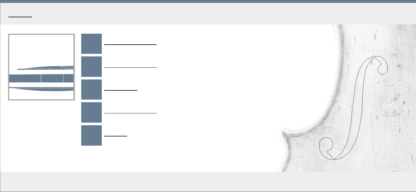
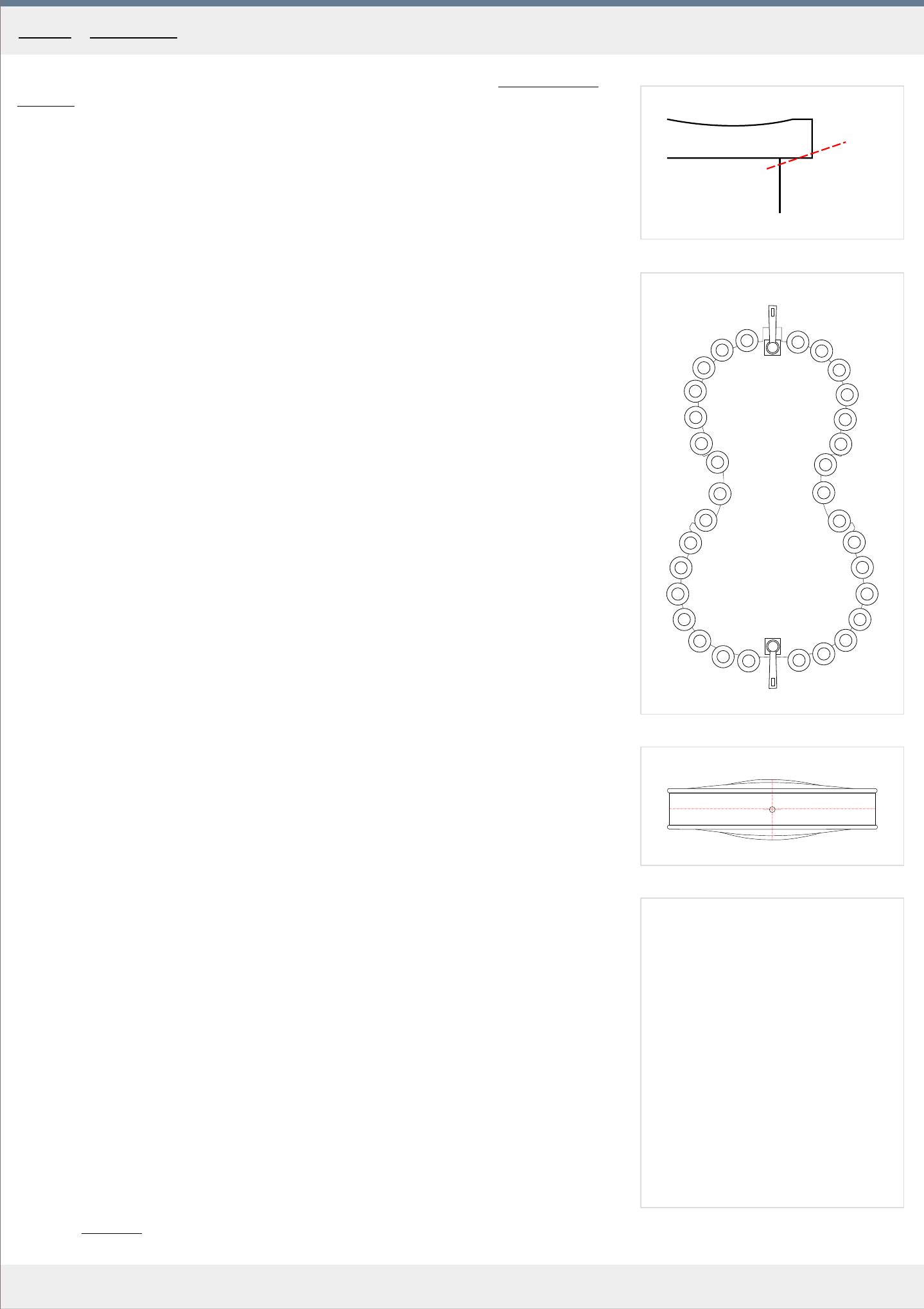
1
2
3
MakingTheViolin.com
Now is a good time to remove the ribs from the mould. For that, refer to the Finishing the rib
structure chapter.
Chamfering the underside
Before gluing the back plate to the ribs, you should create a chamfer on the bottom side (the
first of a series, which will make the edges of the plate round). It goes all the way around the
plate, except for the button. The same chamfer will later be done on the front. See Fig. 1. for
illustration.
1
. Using a suitable file, create the chamfer at about half the distance from the edge to the
ribs' outline.
Clamping the back to the ribs
The back is clamped to the ribs prior to gluing. Self made spool clamps can be used, see the
T
ools section.
1
. Fasten the back plate to the ribs using locating pins.
2. While carefully aligning the ribs to the outline marked on the plate, start adding clamps,
making sur
e you are not over-tightening them. See Fig. 2. for placement. The top and
bottom blocks are clamped with the use of C-clamps. Put some soft-wood padding
between the clamp and the back plate to avoid damaging the plate.
3. Remove the locating pins.
Gluing
1. Prepare medium thickness glue and have a pitcher of hot water, a parting knife and a
brush at hand. P
ut the knife and the brush in the hot water.
2. At one corner, remove a few clamps which will allow you to pull the ribs away and insert
the knife with the glue.
3. Take the knife out of the water and dip it in the glue.
4. Insert the knife in the joint, spread the joint if necessary with your fingers and make sure
enough glue gets applied.
5. Put the knife back in the hot water and remove excess glue with your damp brush.
6. Check that the alignment is right and re-clamp quickly.
7. Repeat with the other corners.
8. Go over the bouts, including the top and bottom block.
9. Let dry thoroughly.
The endpin hole
1. Mark the position of the endpin hole, on the centerline, just 1 mm bellow the horizontal
center of the ribs, see Fig. 3 .
2. Mount the back on the plate holder you used to carve the inside of the plates.
3. Drill the hole using a 6 mm drill bit making sur
e you are drilling at right angles to both the
horizontal and vertical plane of the body of the instrument. Be careful not to split the wood
especially at the end of the drilling.
Category: Assembly
Home - Assembly - Fitting the back
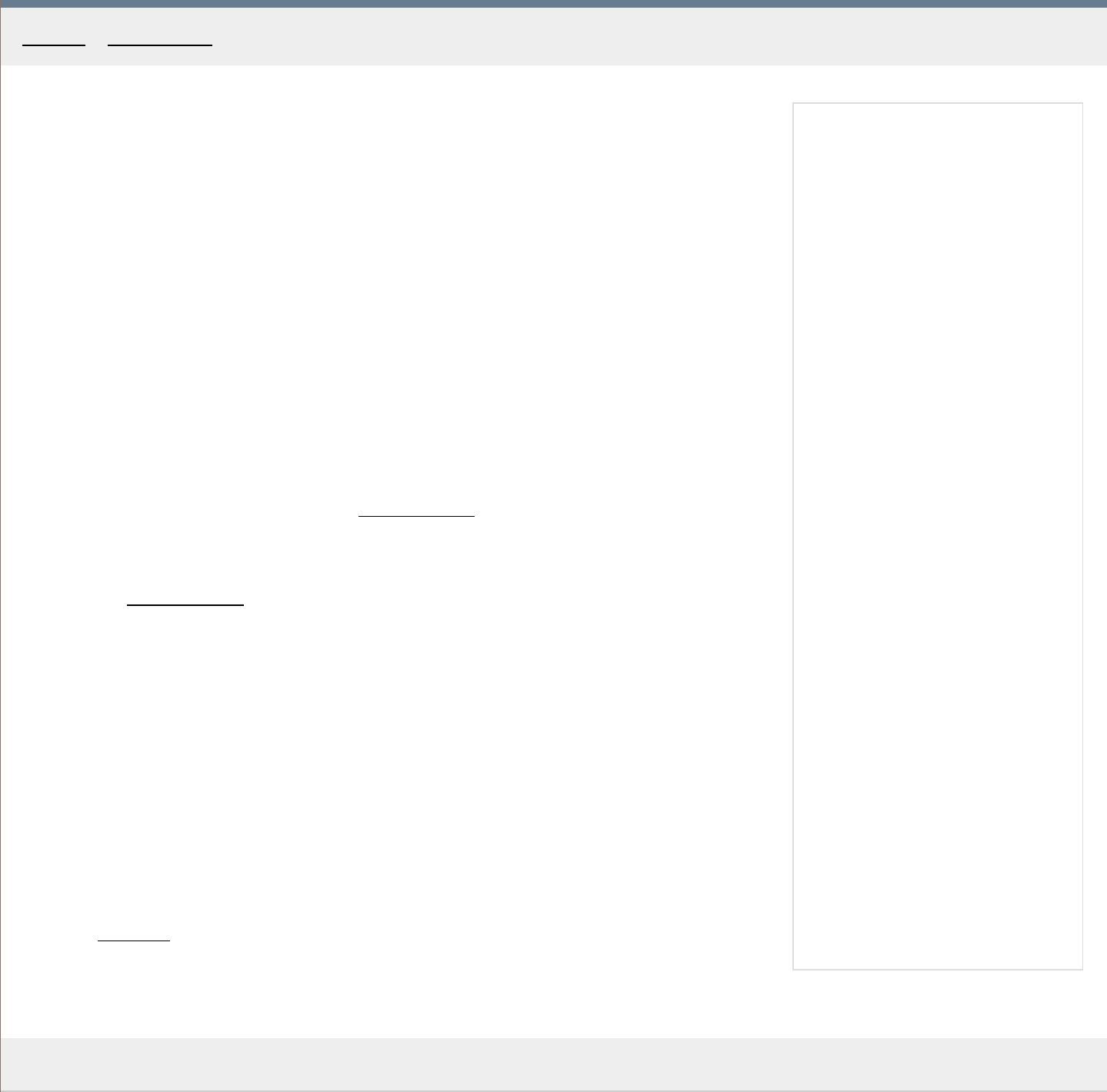
MakingTheViolin.com
Finishing
Before closing, go over all the surfaces that will be after gluing on the inside of the instrument
and make sure there are no loose splinters and other parts that might cause buzzes later on.
Remove remnants of glue, if necessary.
Your label
Before closing, it is customary for many makers to put their personal label inside the instrument.
The labels come in many different shapes and types. Hide glue is used to attach the paper label
to the maple back. The information on the label can be the name of the author, date and place of
creation, the number of the instrument. The position of the label is usually somewhere in the
center part of the back plate so as to be readily seen through the f-holes, but many makers put
their marks also in other parts inside the instrument, ie. on the ribs (Stradivari).
Clamping and gluing the front
1
. Before fitting, the chamfer on the underside of the overhang needs to be done, as it was on
the back plate. F
or this, refer to the page Fitting the back
.
2. The front is glued to the back and the ribs in the same manner as was the back with the only
e
xception of the glue being of thin consistency to ensure easy removal of the plate later on.
Again, see Fitting the back
for the instructions.
Location holes filling
To close the for location holes that are no longer needed, make tiny wooden dowels, spruce for
the top and maple for the back. The easiest way is to use your electric drill to "turn" the dowels
to required diameters. These plugs must go into the holes with ease and should have a point.
1
. Cut four pieces of required wood and create the dowels from them.
2. Put a drop of glue on the tip of the dowel and insert. Repeat with the other holes. Let dry.
3. Using your sharp knife, cut off each dowel as close to the plate`s surface as possible.
Category
: Assembly
Home - Assembly - Fitting the front
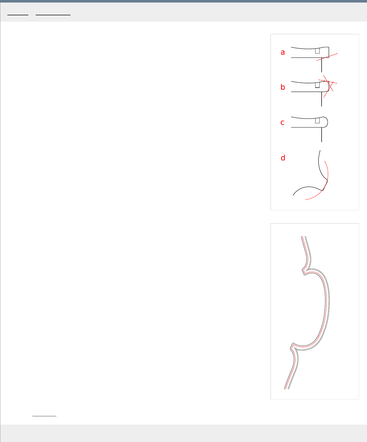
1
2
MakingTheViolin.com
Profiling the edge
Before you proceed with the shaping of the edges, check again that the archings and the flutings on
both plates are perfect.
The overhang for the violin we are building here is approximately 2.5 mm so correct it if its too
much. The chamfer in "a" , see Fig. 1 , should have been done before the gluing of the plates to the
ribs.
1
. Using your file, start with the sequence of chamfers in "b" .
On the back plate, skip the button as it will be adjusted later when the neck has been glued on.
Leave the tips of the corners untouched for the time being.
2. Use abrasive paper to connect the chamfers into a round edge as in "c"
. Towards the tips of the
corners the overhang gets less round, more edgy.
3. Round off the corners a bit, as in "d" .
The corners
The final shape of the cor
ners is created now. It should "go" with the shape and direction of the bee
sting. The overhang at the tips can be a little less, say 2 mm .
The ridge you have created on the outline, continues all the way to the corners, see Fig. 2 . The
fluting naturaly rises to the ridge, from a valley with the bee sting at the bottom.
The points of the corners are usually not as round as the rest of the overhang so do not use a lot of
sandpaper there. Also, the outer tip on each corner is often a little smoother, to emphasize the
visual flow. If needed, make the corners a little sculpted and edgy, using just your scraper or fine
file.
Finishing
On almost all surfaces the last tool that touches them should be the scraper. It gives the wood a
unique texture, expecially in spruce (corduroy). The scraper also allows for greater control over the
subtle features of the corners and the scroll. When removing little scratches and depressions caused
by tools, try applying a little amount of water to them and let dry. Water causes the wood fibres to
swell, filling the nicks.
1
. Go over the arching again and make sure there are no irregularities.
2. Go over the fluting and make sure the area where the fluting connects to the rounded edge is
well defined and sharp. Y
ou can soften the sharp ridge later on if you like, but now it should be
sharp and flow perfectly.
3. Go over the ribs removing any residues of hide glue and generally cleaning up the surface.
4. Go over the f-holes and correct any irregularities using your extra sharp knife.
Category
: Assembly
Home - Assembly - Edgework
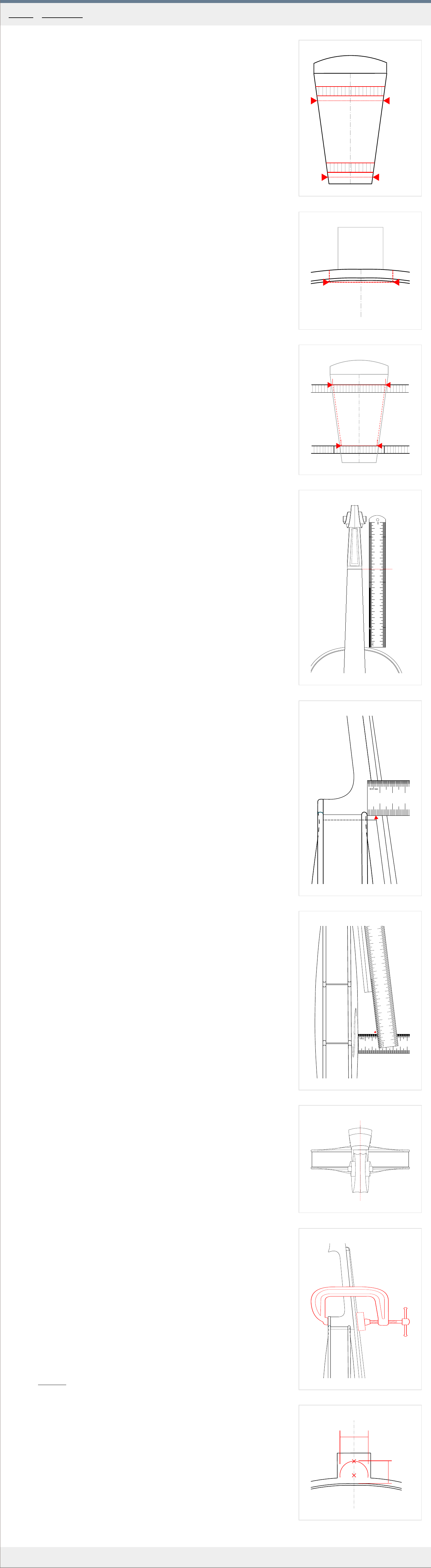
1
a
b
c
d
e
f
2
c
3
c
f
4
1 2
3
4
5
6
7
8
9
10
11 12
13
14
15 16
17
18
19
20
5
1 2
3
6
1 2
3
4
5
6
7
1 2
3
4
5
6
7
8
9
10
11 12
13
14
15 16
17
7
8
9
b
a
MakingTheViolin.com
Fitting the neck
To successfully fit a neck the following set of criteria must be met:
a) 2:3 ratio between neck stop length and body stop length.
b)
Overstand of 6 mm . See
a in Fig. 1 .
c) The center of the neck must coincide with the center of the violin body.
d) The elevation of the fingerboard projected to the bridge position must be 27 mm .
Marking the neck root
F
irst we need to transfer the real widths and thicknesses on the back of the root. See Fig. 1 .
1
. Mark out the "a" overstand of 6 mm .
2. Measure the thickness of the top plate at the overhang, where it will meet the neck root. In
our case its 4 mm . Mark this on the neck r
oot "b" .
3. 2 mm downwar
ds from the top plate is the place to measure the first width for the mortice
"c" .
4. Measure the height of the ribs, 30 mm in our case, and mak
e the mark "d" /29 mm in our
case/.
5. Measure the thickness of the bottom plate, and make the mark "e"
.
6. Finally, 2 mm fr
om the "e" mark is the place to measure the second width, "f" /18 mm in
our case/.
Transferring the widths
With the widths "c" and "f" measured, you can proceed to the violin body to make the neck
mortice.
1
. Set your compass to half of the width "c"
. Using the compass, mark this width at the top of
the plate, from the plate centerline. See the red vertical dashed lines in Fig. 2.
2. With your sharp knife make two incisions on these marks, cutting through the thickness of
the top plate, thr
ough the purfling, to the depth of about 4.5-5 mm . The knife should be a
little tilted, copying the directions of the neck root walls, see the two red dashed lines in
Fig. 3. to get an idea.
3. Connect these two cuts with a straightedge and again use your sharp knife to cut through
the top plate down to the neck block. See the r
ed horizontal dashed line in Fig. 2.
4. Remove the vaste material between these three cuts. Making a series of incisions along
the grain helps.
5. Using your compass again, transfer the width "f" to the top side of the button, close to the
ribs. See Fig. 3.
Cutting the mortice
1. Put your straightedge inside the cut-out in the top plate and make two incisions, through
the ribs, see the two r
ed dashed lines in Fig. 3.
2. Make sure the incisions are deep enough to remove the rib material between them safely.
3. Using a suitable chisel, remove the rib material between the lines down to the button.
Fitting
Bear in mind that small changes in the mortice may cause gr
eat changes in the position of
the neck. Always make sure that when removing material, the walls of the mortice are
perfectly straight for a good fit.
1
. Make a small mark at the top of the top plate at the centerline right where the mortice
starts so that you can check the centering of the neck r
oot to the centerline of the plate.
2. Offer the neck root in place. If the bottom of the root touches the button, cut it a little
shorter so that a gap, lets say, half a millimeter is pr
esent.
3. Measure the basics: Neck stop {130 mm } Fig. 4 , elevation {27 mm } Fig. 5 ,
overstand /neck step/ {6 mm } Fig. 6 and the centering
Fig. 7 , so that you have some
idea from whence to start. The numbers in the curly brackets are your goal towards which
you should carefully proceed.
The elevation is connected to the arching. Thicker tops can have slightly {tens of a mm}
mor
e elevation because it causes the sound to be more powerful.
The overstand is connected to elevation. It should be around 6 mm . On less ar
ched tops it
can be slightly less. Always make sure the fingerboard gets a clearing of at least 2.5 mm
from where the top's arch is nearer to it.
As for centering, it is good to make the mark mentioned above, at the top of the mortice.
Mak
e yet another at the end of the fingerboard so that you can compare it to the
centerline running beneath it in the top plate. These should be perfectly aligned. This is by
no means a substitution for bridge checks, which are the final check of centering.
4. Bridge check for correct centering: With the help of two rubber bands, put the bridge in
place and sight along the fingerboar
d. See Fig. 7 . The fingerboard should be in alignment
with the bridge.
5. Work carefully and slowly towards the aforementioned numbers at the same time making
sur
e the neck root is in good contact with the mortice walls. When being a mm away from
the designed numbers, chalk fit the neck so that when at the final numbers everything sits
perfectly. Bear in mind that the pull of all the four strings tuned to standard pitches is
about 22 kg so a good joint is required.
6. When everything is all right, put on the neck, take a spare bridge, put it on the top plate
right at the end of the fingerboar
d and scribe on its face the fingerboard radius. This helps
you compare the elevation now with the one after you have glued to neck on. It should be
identical which means that nothing went wrong during the clamping and gluing.
7. Clamp the neck down to the violin body and check whether the measurements change.
The elevation should be check
ed with the spare bridge. If the elevation changes it means
that the fit is not perfect and that it changes under pressure so it needs some more work.
Gluing the neck
1
. Prepare medium hide glue.
2. In the meanwhile, try to dry fit and clamp the neck, as in Fig 8. so that you ar
e
comfortable with the procedure and can carry it out as fast as possible.
3. When dry clamped, check the elevation, centering, overstand. If anything changes, you
need to go over the mortice and mak
e corrections.
4. With everything perfect, apply to both the mortice, the button and the neck root itself
ample amounts of hot hide glue.
5. Insert the neck root swiftly in place, squeezing out all surplus glue.
6. Clamp down as in Fig 8. again and let dry over
night.
Marking and shaping the button
See Fig. 9 . The actual dimensions will depend on the violin you are copying. With the
Messiah, the "a" is 17 mm and "b" is 15 mm .
1
. Make a mark at the top of measurement "b" , see the upper "x" mark.
2. Set your compass to half of "a" , put the needle on the centerline (see the lower "x" ), the
compass mark
er on the previously marked point (the upper "x" ) and draw a half-circle.
Check for correctness with your model violin.
3. Start removing material with your knife, checking the curvature of the heel with the neck
template.
4. Using a round file, finish the shape.
Shaping the neck
1. Put the neck template in the middle of the neck underside and move it towards the heel
and chin again to see whether the neck is in good shape. R
emove any irregularities.
2. The final thickness of the neck is 20.5 mm towar
ds the neck root and 18.5 mm towards
the heel so make sure it is close to these numbers. Of course these are general numbers
which may need to be changed based on the size of the player's hand.
3. When the side profile of the neck is perfect, turn the violin around its axis to see the other
surfaces of the oval underside and r
emove anything odd with a flat file.
4. Finish the whole neck with abrasive paper to remove file marks.
Category
: Assembly
Home - Assembly - Fitting the neck
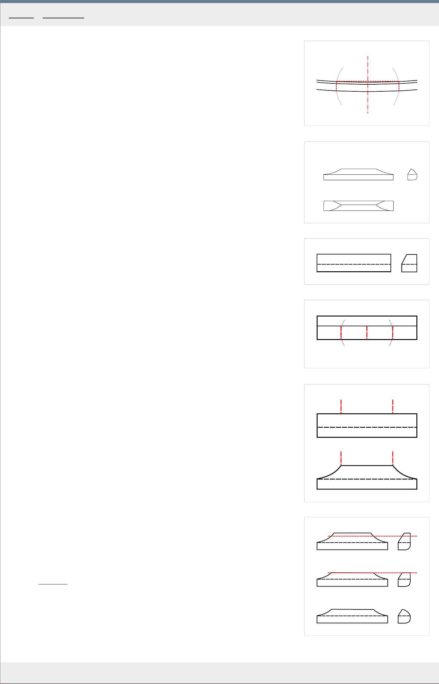
1
a
b
c
2
a
b
c
3
4
a
b
c
5
6
MakingTheViolin.com
Cutting the mortice
1
. Depending on your judgement and the violin you are copying decide what the actual width
of the saddle will be. Usually, its width is between 32-35 mm .
2. Take a compass, measure a half of that width and make marks on both sides of the
centerline as in Fig. 1 .
3. Make two incisions a and b, see Fig. 1 . Using a straightedge mak
e a line c at right angle
to the centerline connecting them. The same as with the neck mortice.
4. Remove the material in the same way as in the neck mortice, down to the ribstock.
The saddle
F
or illustration, in Fig. 2 , you can see the diagram of a finished saddle. View a / front, b /
side, c / top.
1
. Prepare a block of ebony, about 8 x 7 x 35 mm
.
2. Choose what will become the back of the saddle in contact with the mortice in the plate
and mak
e those two sides at right angles to each other, the 8 mm side going up.
3. Cut the ebony block to the correct length so that it fits the mortice easily. Remember that
later on, as the top plate shrinks in dry weather, this block of ebony shrinks much less in
e
xtreme cases causing the top plate to split. So the fit must not be too tight.
4. Put the block in the mortice, make sure everything fits perfectly. If it does, run a marker
ar
ound its front and sides to mark the level of the top plate, see the dashed line in Fig.3 .
5. Plane the front side of the saddle down to the marked level at the angle of about 60
degrees
. See the side view of the saddle in Fig. 3.
6. On the top of the saddle, mark the center c
and from it, using a compass, mark two lines a
and b, 9 mm from the center on both sides. See Fig. 4 .
7. From those two marks, down to the lines scribed in 4, create on both sides shallow slopes
as in Fig. 5 using a knife.
8. Put the saddle back in the mortice and make sure the front and sides run down smoothly
to the plate`s level. Also, mak
e sure the sadle is put in its position without any force. There
should be a slight gap where each of the ends meet the top and the saddle should fall out
if you flip the violin belly down. This rather loose fit hels prevent cracking in the top if the
spruce dries out too much.
9
. Glue in this position using medium hide glue.
Finishing steps
1. When dry, using a file, on the back of the saddle, recreate the outline of the plate. On the
bottom of the back, mak
e it round so that it naturally continues the overhang.
2. Decide on the height of the saddle. Normally its about 3 mm but with higher ar
ches it can
be slightly more.
3. File the top down to the chosen height.
4. Connect the newly defined top with the back with a rounded slope, see Fig. 6.
5. Finish the surfaces using fine abrasive paper. Do not at the same time loose much of the
the crispness.
Category
: Assembly
Home - Assembly - Saddle

MakingTheViolin.com
Prior to varnishing, you should set up the violin in the white and make sure it is playable, and it
doesn't have any buzzes, which could require reopening of the instrument. Only if you are satisfied
with the sound, should you proceed to prepare the surfaces for varnishing.
Preparing the wood surface
1
. Go over the whole surface of the violin and correct areas which you have overlooked before, or
defects arising fr
om manipulation. Be especially careful in the areas where grain sticks out, ie.
overhang and make sure you make these places smooth without loosing the crispness of the ridge.
2. Using a damp wash sponge or cloth, wet the whole violin with water to rise the grain. Let dry
.
3. Remove the grain everywhere using a fine scraper, knife and sandpaper. Be careful on the top
plate where you shouldn't use any sandpaper, just scrapers to not loose the texture of spruce. For
more see the previous chapter on finishing.
4. Redefine the edges and chamfers if necessary.
5. You may now selectively smooth out some of the features, ridges and chamfers if you feel the
violin should look less edgy
. Keep in mind though that the varnish itself will make the edges
smoother.
Tanning overview
Now that your violin is ready we need to make the wood darker which will save us some coats of
varnish and make the varnish look more attractive. At our disposal, we have a number of methods A-
D, which we will discuss here in some detail.
Any of these procedures are best first tried out on scrapes of wood, so that you get the idea about the
amounts and times involved.
A] Sodium nitrite + UV sun ra ys
Y
ou need:
1. 4% Sodium nitrite, 50 ml . T
o prepare, weigh 50 gr of water and add 2 gr of Sodium nitrite.
2. A sunny day or an UVB mercury lamp or an UV cabinet.
The pr
ocess:
1. Put a coat of 4% sodium nitrite on the violin. Mak
e sure the coat is even and there are no drops
left as these would make the wood darker. Don't forget to apply some under the fingerboard as
well.
Sodium nitrite accelerates what normally happens when you put the violin out in the sun. It helps
o
xidize the outer layers of the wood making it look darker.
2. With the fresh /wet/ coat of sodium nitrite expose the violin to UV radiation. For wood tanning
again e
xposure to direct sunlight or a strong UVB light is required.
You have basically three options:
a) Put the violin out in the sun. Get a length of firm string, tie the volute to one end and the other
somewher
e where the sun shines most of the day, ie a tree branch. The violin will rotate this way
ensuring the proper distribution of UV. The only weak spot may be the underside where the button
is, so put a sheet of aluminium foil right under with the distance of about 5 cm. The times depend
on the strength of the sun. In summer a couple of hours should be sufficient.
b)
Use a UV mercury sun lamp, which emits strong UVB. With these precautions must be taken to
avoid dir
ect exposure of any part of your body, eyes especially.
If you have the one bulb mercury lamp you will have to make sure, all parts of the violin get the
same e
xposure. You can coat the whole violin with sodium nitrite at once though. Then expose
different parts. The violin can be dry during exposure but higher humidity levels either in the violin
/freshly coated/ or in the air help speed up the oxidative process of tanning.
For a 250 W att mercury UV lamp about 20-30 minutes from 40 cm distance are enough,
assuming the violin is still damp from the solution.
You will need to rotate the violin every 30 minutes to cover all angles. Don't forget to turn off the
lamp before you do this, or wear UV protective glasses. It takes a whole day to tan a violin this
way.
c) UV cabinet. The black light UVA-B tubes used in varnish curing are usually much slower in
tanning so you will need the white ones which don't block out most of the UVB.
Tanning times for the whole instrument may vary from hours to days depending on the kind of
tubes you ar
e using. Watch for humidity, see the varnishing section.
Sodium nitrite precautions
Though commonly used as food additive (E250), in higher amounts it can be toxic and lethal to
animals and humans. Human lethal dosage is 71 mg/kg, meaning a 65 kg person would likely have to
consume at least 4.615 g to result in death.
UV exposure precautions
Wood tanning by exposure to UV radiation is inherently a destructive process so it should be
practiced with caution. The desirable darkening of the wood is caused by the uppermost layer of the
wood getting oxidized and degraded. The UV light produces ozone, which reacts with the nitrogen gas
present in the air and forms nitrous oxygen. The nitrous oxygen then "burns" /oxidizes/ the wood
leaving it slightly acid.
Precautions!
UVA can cause irritation of the eyes, prolonged overexposure may lead to some damage.
UVB can cause irreparable damage to the retina (welders eye) overexposure may cause sunburn and
skin cancer.
UVC carries seriously increased risk of all of the above and it really should not be used in UV cabinets.
Also any type of UV light will produce some ozone and nitrous oxygen, the UVB/C lamps produce the
greatest amount of these. They both are classified as poisons {depending on concentration} so
precautions should be taken so that the room is sufficiently ventilated.
B] UV sun ra ys
If you want to avoid using sodium nitrite or ar
e unable to obtain it, you can still expose the violin in
the white to sunlight to darken naturally. But there is a catch. Without any accelerator, the violin
takes a considerable time to darken. Exposed to direct sunlight, the stresses in the wood would be
immense, humidity levels dropping which would probably result in numerous cracks. So instead of
baking the violin in the sun, hang the violin somewhere with only indirect sunlight and wait... a couple
of months. This is still possibly the least structurally invasive method, if done properly and if you have
the time.
C] Ammonia fuming
In case you can't or don't want to use sodium nitrite as tanning accelerator, you can use ammonia
fuming instead. This method offers unifor
m colors, color stability, brings out the annual rings in
spruce. The tan can turn a bit greenish. If it is a problem, higher temperatures supposedly get rid of
that. Maple can get less affected by ammonia, applying tea prior to ammonia on those parts can help.
The long-term effects of ammonia on resonant wood are unknown, some makers say it even improves
the wood while others fear it may adversely affect the instrument's structure.
You need:
1. An airtight box large enough to accommodate a violin + a cup of ammonia. The violin should
pr
eferably be hanged.
2. 26% ammonia /laundry grade/
The pr
ocess:
1. Put the violin in the box together with a cup o ammonia.
2. Let it stand for a couple of days, up to five, or until you are satisfied with the color.
D] Staining
Staining can be used as an add on method to complement the tanning methods mentioned above.
Y
ou can stain the bare wood with commercially available stains or use home made stains such as the
black tea stain.
Category: Varnishing
Home - V arnishing - W ood preparation

MakingTheViolin.com
Plaster of P aris ground
Plaster of Paris is produced by the grinding of gypsum and subsequent heating to 150C to get rid of
water. For this recipe, any plaster without additives {resins} can be used.
The recipe:
1
. Put a measure of plaster in a pot. Keep adding water, while vigorously stirring, until you get a
milk
y solution. The large amount of water will prevent the gypsum from setting.
2. Keep stirring for about an hour.
3. Stir /or shake/ every other hour for a whole day.
4. Stir /or shake/ once a day for a whole week.
5. If necessary, add more water so that it stays withing the consistency of, somewhat creamy, milk.
Y
ou have now prepared the ground solution. The remaining plaster can be left in the jar or allowed to
dry to be used on the next instrument. If left dry, just add some water before using it again.
Application:
1
. Put the milk first on the back of the violin, using a brush.
2. Before it sets, wipe off with a towel trying to remove as much as possible rubbing it at the same
time into the por
es. Great care should be taken especially with the edges of the plates and the
areas of the scroll where most of the end grain is.
3. Let it dry. Don`t be alarmed at the plaster-like looks of the instrument at this point.
4. Take your colorless oil varnish. It should be of the viscosity of honey. Apply a patch of this varnish,
the size of a quarter of the plate, with your brush, on the back plate. Right away, wipe off all the
e
xcessive varnish with a cloth so that a silky smooth surface of the color of honey remains. Move
onto the next section.
5. When you are finished with the back plate, you can expose the new ground to UV for about ten
minutes to har
den it. Or if you have a varnishing cradle, just continue on the front plate.
6. Continue to the front panel, then ribs, then the pegbox and scroll. Work in small sections so that
you can wipe off the var
nish before it sets.
7. If necessary, apply to difficult end grain parts more gypsum and wipe off again, repeating the
whole pr
ocess {including varnishing} where needed. The whole surface of the instrument must be
sealed having that silky sheen.
8. Put in your UV box or out in the sun and let dry thoroughly.
Special thanks to the R
oger Hargrave for the recipe and application.
Category: Varnishing
Home - V arnishing - Grounds
MakingTheViolin.com
Varnishing
Your violin should now be the yellow/brown/honey color, the ground properly dry and cured.
Generally, when varnishing, you should watch out for the following qualities: color, darkness,
thinness, transparency.
Color la yer
The next layer is the Madder tincture. Refer to the Madder tincture
section on how to prepare the
tincture. Make sure the tincture is the right viscosity and that it doesn't streak. Test on scrap wood.
1. Put one coat of Madder tincture on the back of the violin. Work quickly, wiping off any excess
tincture with a paper towel. Let dry for at least an hour.
2. If the color looks good to you, apply to the remaining parts of the violin.
3. Let dry for at least an hour or two otherwise you risk dissolving the last layer when putting on a
fr
esh one.
4. Repeat until you think its red enough.
5. Now you can accentuate some parts of the violin with more color. Study other violins which you
consider good looking. The ar
eas with more color are often the C bouts and the scroll. Use a small
brush and/or your fingers.
6. Let dry overnight.
Color oil varnish la
yers
Before you continue, make sure there are no fibers sticking out anywhere. Use a 1200 grade sand
paper to make the surface even. Don't overdo it, you still want to retain the character.
Refer to the section Varnish recipes
for how to prepare an oil varnish. The varnish can be colorized
and darkened:
a) During the cooking / see the recipes.
b) By adding tar / darkening
c) By adding Madder lake / reddening
W
e will use options a and b, namely the Wood ash oil varnish
, which has during its cooking been
already colorized/oxidized by the Wood ash oil varnish which gave it a dark brown-yellow tint and add
some tar the make its color even darker. We may use the option c if the violin seems to want more
red.
1. Pour some of the varnish in a new jar.
2. To make the varnish darker, add a couple of drops of tar and check the result.
3. If the varnish is too viscous, add a little turpentine, stir and check again.
4. Put a drop on the back of the violin to see how it will look like.
5. If you feel its too light, add more tar but be careful not to add too much as that would render the
var
nish impossible to dry. A drop for a milliliter is ok.
6. If you feel it needs more red, get a glass table and mix a couple of grams of Madder lake
into the
varnish. A glass muller is great for that.
Bear in mind though that adding this pigment will decrease transparency of the varnish. It
depends on the size of the particles, so only finely gr
ound pigment should be used. It is also a
good idea to let the bigger particles of the pigment settle in the varnish for 15 minutes before
varnishing.
Put some of the varnish on the glass, add a bit of Madder lake pigment and using the glass muller,
k
eep making circular movements with it to incorporate the pigment into the varnish. You shouldn't
need to press down on the muller, just keep moving it about.
7. When you are satisfied with the color, try some of it on scrap wood and let dry to see how it
behaves.
The varnish before application should have the consistency of fresh paint. Too thick gives you
str
eaks and is difficult to spread, too thin forces you to do too many layers.
Varnishing
1. Using a flat 25 mm wide brush put on the first coat of varnish on the back. Make sure there the
distribution of var
nish is equal without streaks and smudges. Work fast as the varnish starts to
thicken in tenths of seconds. Try to work in areas, quarters which you should make perfect fast to
move to the next area.
If there are smudges or other defects, don't worry, you can wipe off the varnish with a cloth, which
you should have handy at all times.
If you cannot avoid smudges, it can be you are using a brush which is too coarse or the varnish is
too thick or colored.
If the varnish runs, you are probably using too much of it or it is the wrong type. There is a great
amount of calcium in the W
ood ash oil varnish to prevent the running.
2. If you are satisfied with the coat, using your fingers, go over the edge areas, corners and make
sur
e there is no buildup of varnish there.
3. Move over to the top side. Again, work quickly. Make sure there is no buildup at the edges, corners
and especially in the ar
ea of f-holes.
4. On the ribs, use the least amount of varnish here because it tends to collect underneath the
over
hangs and then flow towards the center creating an ugly patch.
5. On the pegbox and scroll again make sure you are using only the amount of varnish necessary. Go
over the pegbo
x holes and collect any varnish buildup there.
6. Take a look a the whole instrument again and correct errors. A different viewing angle helps so
does taking the violin outside and inspecting it under the sun.
7. Put the violin in the box or outside to dry. Allow at least a day or two per layer.
8. Use your finger to check how the varnish is curing. When it ceases to be sticky to the touch, you
can go over the surfaces r
emoving any zits and dirt with your nail. The varnish is considered
sufficiently dry when your finger leaves no fingerprint in it after mild pressure for a couple of
seconds at room temperature.
The number of color varnish layers depends on the thickness of the layers, their colorizing effect and
common sense which says that less varnish, if possible, affects less the sound of the instrument. With
medium thickness varnish layers, three should be enough, supposing the violin has been properly
tanned and received some layers of Madder tincture before.
Drying
Oil varnishes need UV light to speed up the oxidization of oil. It is best and often fastest to put the
violin out in the sun. For this, get a length of firm string {a fishing synthetic line is great} and attach
it somewhere, where the sun shines most of the day. A tree branch is great. At the other end create a
noose to hang the scroll of the violin on. The violin should freely rotate in preferably a light breeze.
It is important to keep checking the state of the varnish and the violin as a whole. A strong sun,
especially without wind can make the violin very hot which can result in dehydration, cracking or
blistering of the varnish.
Whenever there is insufficient sunlight, the usage of an UV box is preferred. Check the UV cabinet
building section for more info. The cabinet should be spacious enough to allow plenty of fresh air
around the hanging violin. Ventilation must be installed /in and out fans/ to supply that fresh oxygen
needed for the catalysis process taking place in the varnish and also to prevent the violin from
overheating and overdrying and cracks from forming. The key is to keep the temperature inside as
low as possible. Putting a bowl of water at the bottom is a good idea, but it will not do much good if
the temperature of the instrument itself is too high.
It is a good idea to measure the humidity inside the cabinet. In my cabinet it can get as low as 30
percent so I keep to limit the time the violin stays inside the box as much as possible with breaks /ie.
outside during the day and in the cabinet at night/.
Either way, the varnish drying is, along with tanning, the most stressful time for the new violin so
bear that in mind and check often.
The drying times are obviously based on many factors. For this reason to make sure every layer is dry
enough, press your finger on in for a couple of seconds to see whether it leaves a print. By leaving a
print I mean that the varnish will get visibly grooved not that you just leave a fingerprint as on a glass
window. If the varnish is still plastic, it is not sufficiently dry. Repeat the test in different areas on the
violin, especially if you have a reason to think that certain areas received less UV than others, ie. in
the upper curves of the C bouts.
Oil varnish finishing la yers
Put on a coat or two of your colorless Wood ash oil varnish
to form a protective layer. Following the lean to fat principle, this varnish should
have somewhat more oil in it, making it slightly softer.
Category: Varnishing
Home - V arnishing - V arnish

MakingTheViolin.com
Testing the varnish
1
. Go over the whole surface and remove zits.
The var
nish must now pass the print test in all areas.
1. Hold you finger on the varnish using moderate pressure for a few seconds and see if it
imprints, and you can see the fingerprint imprinted plastically into the varnish.
2. Check in the areas of C bouts again, especially the upper C bouts sometimes have a hard
time drying because of limited UV access. The ar
eas where the varnish still imprints can
be exposed to UV selectively, using a mercury lamp. 20 minutes is usually enough.
3. When the varnish doesn't imprint it is ready to be polished. With the varnishes used in this
manual, this may be in about a day or two af
ter the last coat.
Polishing
The goal of polishing is to remove: a] the errors in the varnish, small zits etc., b] that cheap
sheen which comes with new varnish. At the same time you want to retain some of the
surface's character and that of the wood underneath.
You need a cloth, mineral oil and tripoli.
Start on the back of the violin. Again, you want to remove most of the zits, and some of the
"orange peel" texture. You don't want to make the surface look like a piano.
1
. Take the cloth dip it in the oil and tripoli.
2. Using circular movements start polishing the whole surface. Make sure you cover the area
evenly
. Feel for any coarser particles under you fingers and remove them if found, as they
might scratch the surface. Be careful in the areas of corners and the purfling edge as here
you can easily cut thru the varnish.
3. When done, clean up the surface with a paper towel and see what it looks like. The oil
r
esidues will make the surface look somewhat unnatural, satin like, but you should get an
idea about how the surface looks like. Again, don't overpolish.
4. If you want to remove the oil to see how the finished surface will look like, use a wet paper
towel or a towel with flour as medium.
The same applies to the ribs.
On the fr
ont you may want to use a movement which goes along the growth lines which may
have created a "corduroy" effect in the varnish which you don't want to remove. Again, be
careful not to overpolish, just get rid of the zits but not the texture.
The same goes for the scroll.
1
. When finished carefully remove the remnants of tripoli from all nooks.
2. Wash down with a wet towel or flour again to see the final sheen.
3. Let dry for a few hours to get the final look.
F
-holes and pegbox staining
You can now decide, whether you want to make the inside of the pegbox and the f-holes any
color or not. Some makers leave these parts just varnished, others stain or paint them. If you
want to paint them, here you go:
You need a tube of artist's oil Burnt umber color, turps and a fine brush.
1
. Squeeze out some of the color and make if of the desired consistency adding a little
turpentine.
2. Paint the inside of the f-holes and remove any excess color on the top surface with a
towel.
3. Paint the inside of the pegbox.
4. Let dry for a couple of days. The painter's oil colors have a comparatively long drying
times. UV light doesn't help her
e. You could use some dryer additives to speed up the
process, if you really need to.
The color, especially in the pegbox, can really be very thin, it doesn't have to necessarily
cover a hundred percent. Think more about smearing the surface than putting a coat of paint
on it.
When you are finished here, you can continue to the Peg fitting
.
Category: Varnishing
Home - V arnishing - Polishing

MakingTheViolin.com
In this varnish, you have the option to use nitric acid to color the resin. If you decide not to
use the acid, skip step 2 in the Preparation. The varnish will be less colored and great for the
finishing coats.
Equipment
1. Hot plate preferably thermostatically controlled, with diffuser screen.
2. Thermometer. (maximum of 350° C will suffice). A candy thermometer or a cheap Radio
Shack multimeter with a ther
mometric probe.
3. An enameled or stainless steel pot.
4.
Lab spoon or glass rod for stirring.
5. Scales.
6. Coffee filters.
7. Fire extinguisher. (ready at all times)
8. A pipette or a dropper.
Ingredients preparation
Liquid wood ash
1. Burn preferably hard woods, a mixture of spruce and maple shavings is acceptable.
2. Put an amount of ash that is equal of that of resin {200gr} in a coffee filter.
3. Pour an equal amount of distilled water {200gr} in the filter and wait until all the water
gets filter
ed.
Linseed oil thick ening
Cook 170gr of linseed oil for 1.5 hours - until it gets thicker and considerably darker.
Ingredients
1. 120gr Damar, 80 gr Calophony.
2. 65% nitric acid.
3.
Linseed oil or Walnut oil Cold pressed.
4. 200gr Liquid wood ash.
5.
1/2 teaspoon - Slaked Lime.
6. Spirits of Gum Turpentine.
Preparation
1. Put 120gr of Damar and 80 gr of Calophony in your pot. Bring to 100C.
2. Bring to cca 170C and start adding 65% nitric acid. A pipette or an eye dropper are great
for this. 50gr should be enough. A
dd a little, let bubble, stir, and when the reaction subsides,
add more. {you can skip this step to obtain clear varnish}
4. Add 200gr of Ash water + 1/2 spoon of slaked lime, keep stirring.
5. Boil off all water.
6. Bring to 280C and boil for 10 minutes.
7.
Thicken 170gr of linseed oil.
8. Warm up resin to 270C, add thickened oil.
9. Cook at 300C for approximately 30mins or more, until a successful string test, see bellow.
10. Remove from heat, warm up 100gr of turps to 100C.
11. Add stirring to 140C varnish.
Advantages
Gives a deep yelow/r
ed/brown transparent color. Stable colors.
Disadvantages
Some people say the nitric part may negatively affect the varnish in time. If that matters to
you, just don't add any.
String test
The string test gives you an idea about how well the resin gets bonded with the oil. A failing
string test means insufficient bonding.
1
. Place a drop of hot varnish into a glass of water, let cool for 5-10 seconds, pick up and
pinch between your thumb and inde
x fingers. As you pull your fingers apart a string
should form.
2. Failing that, continue cooking until varnish strings. The longer strings it gives you, the
better
. 5 cm would be great.
Category: Varnish recipes
Home - V arnish recipes - W ood ash oil varnish
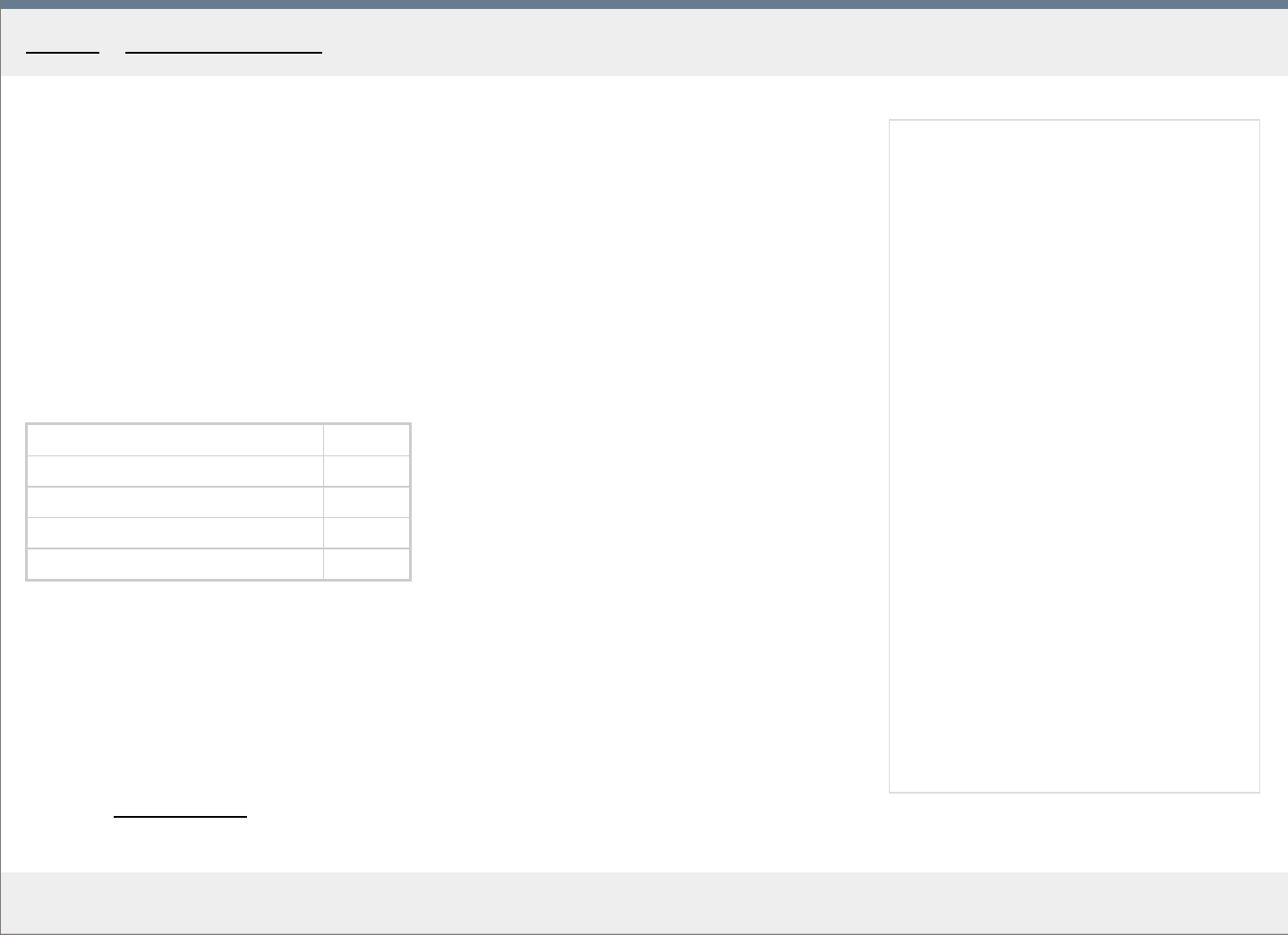
MakingTheViolin.com
Madder tincture
Preparation
1. Steep Madder, Pernambuco and Tea {tannic acid serves as mordant} in warm alcohol for
two days, in separate jars.
2. Concentrate the Madder tincture to one half by letting some of the alcohol evaporate.
3.
Solve some ruby shellac in alcohol. Can be any alcohol soluble resin, such as shellac,
mastic, sandarac, V
enice turps. etc.
Putting it together
Madder tincture thickened to 1/2 30 gr
Pernambucco tincture 10 gr
Tea tincture 5 gr
Shellac ruby 10 gr
Ammonia / reddening 10 drops
The resulting tincture should have such viscosity which will allow you to brush the coat on
without streaks but on the other hand not so thin that you would have to put on many coats.
The ground you use needs to be either neutral or slightly acidic and the varnish you use over
the tincture should also be either neutral or acidic or an isolating layer of varnish can be
applied.
Category: Varnish recipes
Home - V arnish recipes - Madder tincture

MakingTheViolin.com
Madder lak e preparation
This recipe is for those who want to prepare their own oil color from raw chopped madder
root. You can as well skip this process and buy Alizarin Crimson oil color for painters.
Equipment
1
. Enameled pot of at least 3 L capacity, {the solution must not get in contact with ir
on,
similarly various glass cookery is not recommended, they may crack and spill the
potassium carbonate}
2. A plastic bucket, preferably of white color to easily identify the sediment, cca 10 L
capacity
.
3. A precise thermometer, connected to an electronic relay which will turn the hotplate on
and off to maintain a steady temperatur
e.
4. A suction hose.
5. A funnel with coffee filters.
6. An empty bottle.
Ingredients
1. 180 gr chopped Madder r
oot.
2. 60 gr P
otassium carbonate.
3. 60 gr P
otassium alum {Aluminium potassium sulfate}.
Preparation
1. Add 2400 ml of tap water into the pot
2. Add 60 gr od potassium carbonate and let dissolve.
3. Add 180 gr chopped Madder r
oot, stir thoroughly.
4. Bring to 40°C for 36 hours
. The temperature must not exceed 45°C for longer periods of
time, otherwise the temperature sensitive Alizarin will turn brown. You may try to set 40°C
on the thermometer and make its tip touch the bottom of the pot. Also, set the hotplate to
its lowest setting. Stir occasionally.
5. Put a filtering cloth into a plastic bucket, put a sieve onto the bucket and pour the Madder
r
oot solution in it. Wring all the liquid out of the chopped root, remove the sieve.
6. Carefully lift the filtering cloth, tie it with a length of wire and hang it on a wooden stick
acr
oss the top of the bucket.
7. Let it drain for a while and then squeeze out the rest of the lake.
8. Put 1200 ml of water into your empty pot and war
m it up a bit {40°C}.
9. Add 60 gr of alum, stir until dissolved.
10. Add the resulting warm solution into the bucket with the drained Madder pigment and stir.
The solution should fr
oth profusely.
11. Stir occasionally for 3 da
ys .
12. Add fresh water to the solution so that you fill the bucket to its brim.
13. Let it stay for 36 hours
.
14. Drain the semi-clear water with a suction hose, stay well of the line of the sedimented
pigment. If you ar
e uncertain about the line, remove just one half of the bucket. Refill with
fresh water and let the pigment settle for 24 hours .
15. Decant again and refill with water. Let it stay for 8 hours
.
16. Repeat until you start draining clear water.
17. Put a funnel into an empty bottle. Put a coffee filter in the funnel. Pour the sedimented
pigment fr
om the bucket into the filter.
18. Let it filter for a couple of hours, or until the water no longer drips from the funnel.
19. Collect the sediment into a jar and start drying out, stirring occassionally.
20. When the paste gets too thick add a bit of thickened linseed oil and mix it in thoroughly.
21. Continue stirring and letting the mixture stand until it thickens, and adding more oil to
k
eep it pasty. After maybe a week you should be left with just oil paint.
Consider warming up the paste if you want to speed up the process {40°C max}. To test that
there is no water present in the paste, put a little bit on your finger and spread it on a smooth
surface. If there is water, the paste will coagulate in a typical "watery" manner, if the water
has been sufficiently removed, you will easily create a consistent "oily" layer on such a
surface.
This smooth paint can then be directly added to your oil varnish.
Category: Varnish recipes
Home - V arnish recipes - Madder lak e

MakingTheViolin.com
This varnish is great touch-ups. Should you need to correct anything after your oil varnish has
dried, use this spirit varnish.
Equipment
1. Hot plate preferably thermostatically controlled. {for hot preparation}
2. A pot with something at the bottom to put the jar on. {for hot preparation}
3. Scales.
4.
Cloth or pantyhose filter.
5. Glass jar.
6. Small jar.
Ingredients
1. 180gr ground Seedlac.
2. 30gr ground Sandarac.
3. 30gr Elemi.
4.
15ml Spike lavender oil.
5. Spirit
Preparation cold
1. Put all the ingredients in a jar and let dissolve for 2-3 days.
2. Shake occasionally.
3. Decant through a cloth or pantyhose.
Preparation hot
1. Put the Seedlac and Sandarac into the jar.
2. Fill the jar with spirit, just enough to cover the resins. Put on a lid, but don't screw it.
3. Put the jar into the pot.
4. Put the pot on the hot plate.
5. Fill the pot with water as high as the contents of the jar.
6. Turn on the hot plate.
7. Keep the water about 80 degrees for about 1-2 hours. Shake the jar occasionally.
8.
When almost all the resins dissolved, turn off the hot plate.
9. Put the Elemi and Spike oil in the small jar and put it on the hot plate.
10. Stir occasionally until the Elemi dissolves.
11.
Pour the warm Elemi/Oil solution into the warm Seedlac/Sandrac solution.
12. Decant through a cloth or pantyhose.
Category
: Varnish recipes
Home - V arnish recipes - 1704
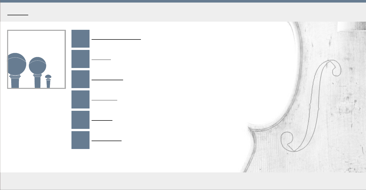
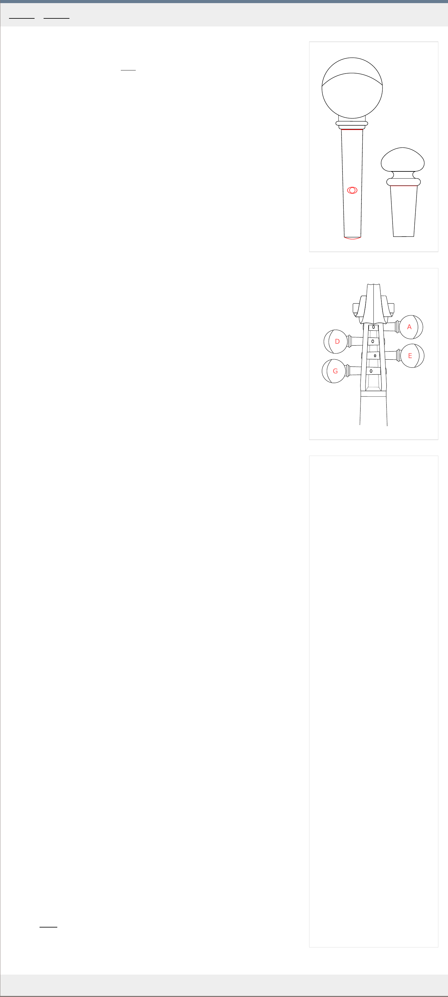
1
2
MakingTheViolin.com
The pegs
To turn the pegs to a proper diameter you need a well adjusted peg shaper. I recommend the
four hole shaper by Herdim. See the Tools
section for more information.
Shaper setup
1. Make sure the shaper blades are very sharp {if sharpening, make sure the blades are
r
esharpenable, HSS, not just surface hardened} and also that they project over the holes
by 0.25 to 0.75 mm . They should also project over the fron side of the mouth opening by
approximately 0.5 to 1 mm . This will allow for a close shave with no tearing.
2. Also, you need to make sure that the shaper blades are set to an angle that is perfectly in
line with the holes the r
eamer does. For this, lightly insert the reamer with the round
smooth part up and try to set up the blade in the shaper so that it both protrudes
minimally, and is in line with the reamer.
3. You need to test the alignment on some scrap wood. Drill the 6 mm hole, pr
eferably in
maple, drive the reamer through it and shape a piece of hard wood, preferably ebony to
match it. Put the shaped peg in the hole, turn quickly, pull out to see whether there is
contact along the whole length. If there is, you have your reamer and shaper matched.
Shaping the pegs
1
. Using a knife, make an incision around the circumference of the peg, right next to the
collar
. See the red line in Fig. 1 .
2. Insert the peg blank into the first hole where the shaper bites and start turning slowly.
3. Proceed to the smallest hole (8 mm width at the top here), again turning slowly and
watching for any tear out, until you get to the collar
. If for some reason the turning is not
as smooth as you would wish, use a bit of dry soap for lubrication.
4. Repeat with the other pegs.
Reaming the pegbox holes
1. Insert the reamer into the smallest hole of the shaper and make a mark using a
per
manent marker about 1 cm in on the reamer. The initial reaming will be done up to this
mark.
2. Insert the reamer in the first hole. See Fig. 2 for the or
der in which the pegs are
positioned in the pegbox. Start turning the reamer while maintaining perfect vertical and
horizontal alignment. When you have reached the previously made mark on the reamer,
stop.
3. Insert one of the pegs, turn a few times. At this point the distance from the pegbox wall to
the collar should be about 15 mm . R
emove the peg to see whether the pegbox walls have
left the shiny rings on the peg meaning there is a full contact with the holes.
4. Repeat with the rest of the holes.
5. Again, insert the pegs in their respective holes turning each quickly a few rounds. Then
tak
e look at each of them to see whether they are in perfect contact with both pegbox
walls. A perfect contact is necessary for the pegs to be able to securely hold the pull of
the string.
6. If all is fine, continue carefully reaming each hole so that the inserted pegs` heads are just
a little bit over 10 mm fr
om the pegbox walls.
7. Turn again each of the pegs a couple of times to drive them home. This will be their final
position.
Finishing the pegs
1. Using your scribe, make a mark about 4 mm in fr
om the inner pegbox wall at the side of
the peg's head. Repeat with the remaining pegs. Make sure the marks are well centered.
2. At each mark, drill a 1,5 mm hole for the G, D, A strings and 1 mm hole for the E
string.
3. Using your small round (needle) file, with a few strokes, create an in-set bevel at each of
the openings. See the r
ed elipse around the hole in Fig. 1 .
4. Now you need to trim the pegs to their correct lengths, almost flush with the pegbox
walls. T
ake a scribe, put it on the peg shaft, right next to the pegbox wall on the side
where the peg needs trimming. Turn the peg a few times, making a mark on it. Repeat
with the other three.
5. Cut the pegs to their new lengths. To smooth out the ends and create the bevel, put a
sheet to fine (600 grit) abrasive paper on your workbench and start making (drawing)
cir
cles from small to wide (a kind of a spiral) until you end up with a regular bevel. Finish
in the same way on a yet finer paper (1200 grit). Burnish on a piece of linen (your pants).
Installing the endpin
To shape the endpin, the general rules described in the peg section apply.
1
. Assuming your equipment is set up properly, take the endpin blank and shape it in the
lar
gest hole available, which will produce an even shave.
2. Ream the end pin hole again with regard to maintaining horizontal and vertical alignment.
Check the diameter constantly r
einserting the endpin.
3. When the endpin is about 1 mm fr
om being fully inserted stop. Put a bit of dry soap on it
and carefully try to insert it fully. The endpin must sit in its position securely yet must be
easy to remove so avoid using excessive force to drive it in. If necessary, ream the hole A
LITTLE and try again.
Category: Setup
Home - Setup - Pegs and endpin
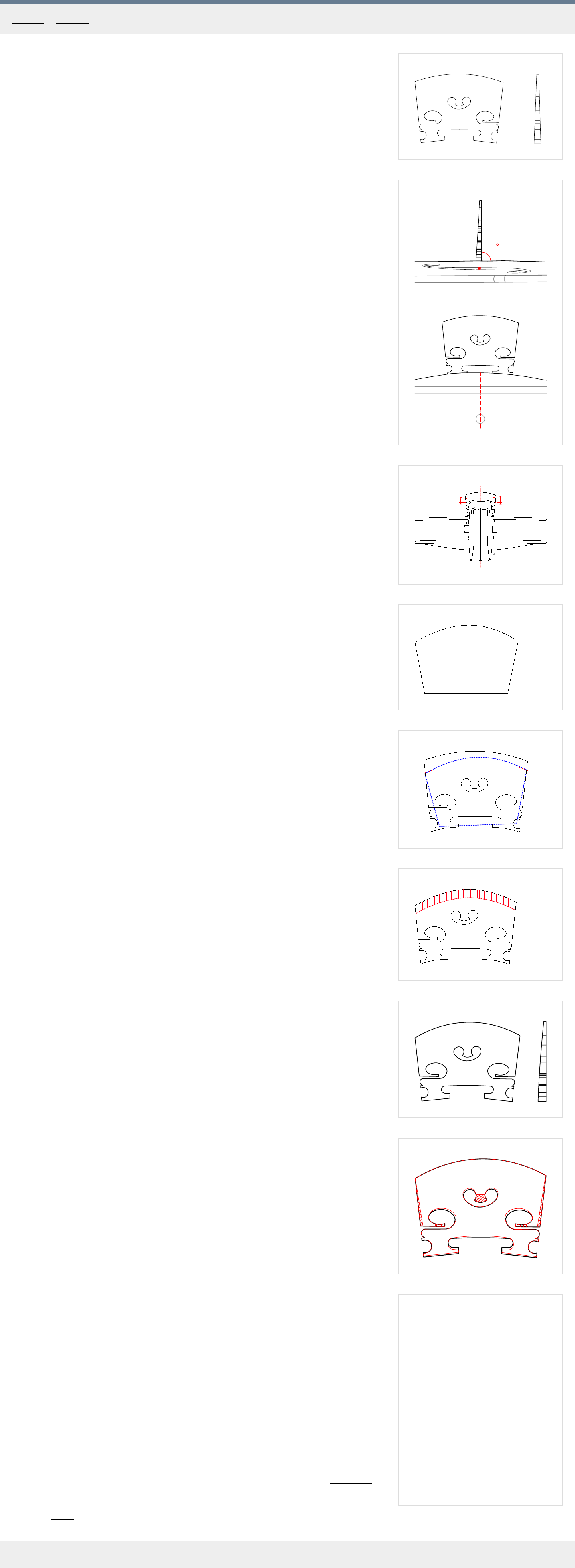
1
2
90
3
e
g
7 mm
5.5 mm
4
e
g
5
e
g
a
b
6
e
g
7
4 4 4 4
4.5 4.5
3.7
2.5
2.5
2.5
8
MakingTheViolin.com
The bridge
The bridge, made of maple, serves the purpose of upholding the strings and transmitting the
vibrations from the strings to the body of the violin. As such it must be both robust enough to
withstand the pressure of the strings and light enough to transmit the vibrations freely.
Normally, you buy a bridge blank 41,5 mm width for the 4/4 violin and carve it to get the
best sound. See Fig. 1 for a typical bridge blank.
The position of the bridge is marked by the inner nicks in the f-holes. The back of the bridge
should be at right angles to the top plate, the feet of the bridge should be in perfect contact
with the arching. See Fig. 2 . for the correct bridge position.
You also need to decide which side of the bridge is the front and which is the back. The
medullary rays on the back side should have more dots than slashes.
The bridge feet
1
. Make sure the back of the bridge is flat. Use fine abrasive paper on a flat surface and rub
the back of the blank on it.
2. Turn the bridge over and in the same manner rub its front to get the thickness of 4.7 mm
at the feet. T
o get to the 4.7 mm at the feet faster, you can use a sharp block plane
(maybe holding it in your left hand upside down, while holding the bridge with the other)
but be extremely careful not to chip away any of the fine tips and of course not to cut
yourself. Keep checking the thickness often as it is easy to over-thin the feet this way.
3
. Now to transfer the arching of the plate onto the bridge feet, put the bridge in its position
and put a thin strip of paper or plastic (no mor
e than 0.7 mm) on the arching, behind the
feet. Take a fine pencil and with moderate pressure, transfer the outline onto the back of
the feet.
4. Now use a sharp knife and start removing the wood along the lines (always cut towards
the bridge center to avoid chipping). K
eep putting the bridge on the violin and work
towards the back of the bridge being at right angles to the violin top. At the same time try
to eliminate the gaps so that the bridge "sits" in full contact with the arching. Keep fitting
until the bridge has no gaps.
5. Get a strip of thin paper 2 x 6 cm . T
ake a soft graphite pencil and rub off as much graphite
as possible on the paper where the bridge feet touch it. Blow off the excess graphite.
6. Put the paper strip on the violin top where the bridge should be, put the bridge on top of it,
in its pr
oper position and move half a millimeter from side to side to rub off some of the
graphite on the bridge feet. Use only moderate force to avoid bending and inaccurate
readings.
7. Remove wood where the graphite got rubbed on. Take your time. To remove just a tiny
sliver, moisten the wood ther
e a little. For the tiniest amounts use the knife to scrape the
wood, rather than cutting it. Don't stop until the feet are in perfect contact with the top. At
the inner tips of the feet, aim for about 1.5 mm in thickness.
Again, the perfectly sitting bridge has its back at right angle to the violin's top, is in full
contact with it so that it doesn't rock when you lightly tap the violin body (the bridge freely
resting on its feet, in its proper position).
The bridge arch
1
. Put the bridge in position with the help of two rubber bands, each band fastened to the
foot at one end and to the upper cor
ner of the back plate at the other.
2. Sight along the fingerboard and mark its projected ends on the E and G side on the bridge.
See
Fig. 3 for illustration.
3. Remove the bridge and offset the previously made marks 4.5 mm higher on the E side
and 5.5 mm higher on the G side. Again see Fig. 3 .
4. Create the bridge template in Fig. 4 . The template is best made of a sheet of plastic or
aluminium. P
rint Fig. 4 out and transfer the outline onto the sheet. Cut out and refine the
edges.
5. Using the template, connect the offset points "a" and "b" , as in Fig. 5 . The blue dotted
shape is the template her
e.
6. Remove the wood from the top of the bridge down to the template line with your knife.
Always cut "downhill". R
etain an angle that is equal to both the front and back. Recheck
with the template and use a fine file to finish the arch for now.
7. Pare away the wood on the first 5 mm cr
eating a taper of 1.2 mm in thickness at the top
using a knife. Again, "downhill" cuts only. See Fig. 6 . Finish with a file.
8. With your Vernier caliper transfer the width of 33-34 mm onto the top of the bridge. P
ut it
slightly to the G side as you did on the nut.
9. Use a needle file to create shallow grooves.
10. Fit the G and E strings to adjust their heights. They should be 4.75 mm /G/ and 3.75 mm
/E/, measuring their elevation at the end of the fingerboar
d. Make the strings somewhat
tight for the true elevation to show, but not too tight to avoid bending the top, especially if
you don't have the sound post in place. File away the wood under these strings, keep
renewing the grooves until you get to the numbers. Make sure you don't drift from the
position.
11
. Restore the bridge arching by retracing the template and removing the wood and reshape
the top to 1.2 mm again.
12. Mark the remaining two D and A string grooves equidistantly (cca 11.5 mm width) in
between the G and E gr
ooves.
Finishing the nut
With the strings on, take a look at their distance from the fingerboard at the nut. It should be
0.8 mm for the G string and slightly less 0.6 mm form the E string. Lowering the action here
will lower the string distance overall, so check again the end of the fingerboard.
The grooves should be quite shallow, only one third of the string covered, so refinish the arch
of the nut accordingly.
The front of the bridge
See Fig. 7. for the final thicknesses of the average bridge. To remove wood, you can use the
bridge holder and a chisel or you can just hold it in your hands paring away the wood with
your knife. For thicknessing, Vernier caliper can be used or the thicknessing gauge you used
in the thicknessing of the plates.
Finalizing the contour
Fig. 8. shows you where to remove wood when finalizing the contours. Be especially careful
when cutting the central part of the heart as chipping easily occurs. The left and right
chamfers are always cut from bottom up to avoid chipping.
Burnish the bridge using a piece of paper with a bit of dry soap.
The weight of the finalized bridge ranges usually slightly above 2 grams. See the Soundpost
section for the possible relationship between the bridge and the soundpost.
Category: Setup
Home - Setup - Bridge
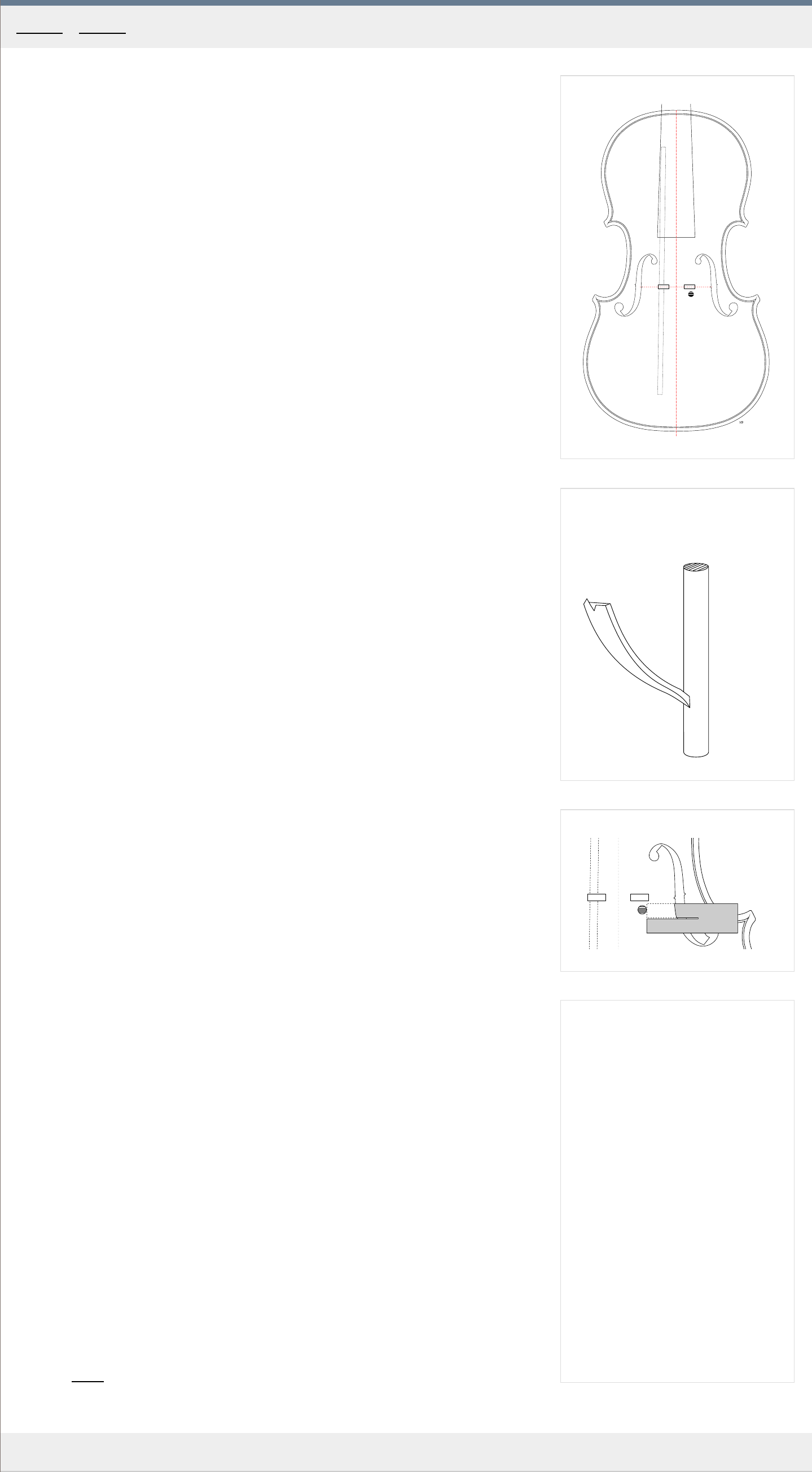
1
2
3
MakingTheViolin.com
Measurements
The diameter of the finished soundpost is about 6 mm . The length depends on the arching,
but may be a little above 50 mm in most cases.
To measure the required length of the soundpost, insert a pencil (or the soundpost blank) in
the right upper f-hole eye at the right angle to the plane of the violin, until its tip touches the
back plate. The point on the pencil level with the top of the arch at the center of the violin
denotes the approximate length needed.
Choosing the wood
You need good quality spruce. It should be straight, and to ensure it has no runoff, it should
be split. It should also be dense enough - ideally have around 5-6 annual rings in its final
diameter (6 mm). The wood for the top plate is usually good for soundposts, but it varies in
density, so split off a piece that has the required number of rings and is approximately 8 x 8
mm wide. The length of about 70 mm should be enough.
Now you need to round the stick, either by turning on a small lathe, or using your hand drill
clamped in a vice, the stick fastened in stead of your regular drill bit. Use coarse {80}
sandpaper and wrap it around the turning stick to remove material. Keep moving the
sandpaper up and down the stick to achieve consistent thickness. When you have reached 6
mm everywhere, you are finished.
Or you can, of course, buy the soundpost blanks pre-made.
Cutting the soundpost
Use a razor sharp knife. Avoid files even though they may seem easier to work with in the
beginning. The knife gives you the precision and flexibility needed. You know how much wood
and where you have removed.
To cut the soundpost to its length, roll it on the table while making a cut around its
circumference. When the cut is deep enough, you can break the soundpost off.
Now, to start fitting the post, you can try to insert it starting somewhere on point A. It will still
be too long, so you will not be able to insert it farther to the side, to its final place, see Fig 1 .
Using a knife, the soundpost resting on your workbench, cut a sliver of wood from both ends
and reinsert again. Try to get a feeling for this, do as many cuts as possible, trying to get thin
slivers, to get the hang of it. You should be able to remove just part or the diameter or a
whole consistently thick wafer if needed.
Fitting the soundpost
The default position for the soundpost is about 2.5 mm behind the treble foot of the bridge,
see Fig 1 . You should aim to reach this position before adjusting the soundpost to change the
sound.
The soundpost is held in position with the help of the soundpost setter, as in Fig 2 While the
soundpost is inserted, you may keep the setter attached to the soundpost for easier
manipulation.
This requires patience. Keep cutting and reinserting, inspecting the fit, also using the
inspection mirror for parts where you cannot look. Perceive how both the top and the bottom
plates are angled as you proceed more to the right side. The goal is to get the soundpost
approximately in the position in Fig 1 standing at right angle to the plane of the plates, in full
contact with the plates. Again, make sure the soundpost is perfectly perpendicular to the
violin plane, both when you see it through the f-holes and the end-pin hole.
You can measure the position of the soundpost relative to the bridge foot using a simple strip
of thicker paper, cut in the middle, as in Fig 3 .
Finalizing the position
Once you have reached the default position. Check everything sits perfectly, both through
the f-hole and the end-pin hole, using the mirror. It is important that the soundpost be put in
its default position with just light force.
You can now put on a set of strings together with the bridge and try the sound of the violin.
The soundpost serves as a kind of fulcrum for the top plate so its position influences the
action of the plates, the bridge and the strings. With this in mind, you can change to a certain
degree the timbre of the violin (and playability). With the soundposts position you not only
change the spatial relationship between it and the moving parts but also the tension. The
more east you go, the more tension you get.
Category: Setup
Home - Setup - Soundpost
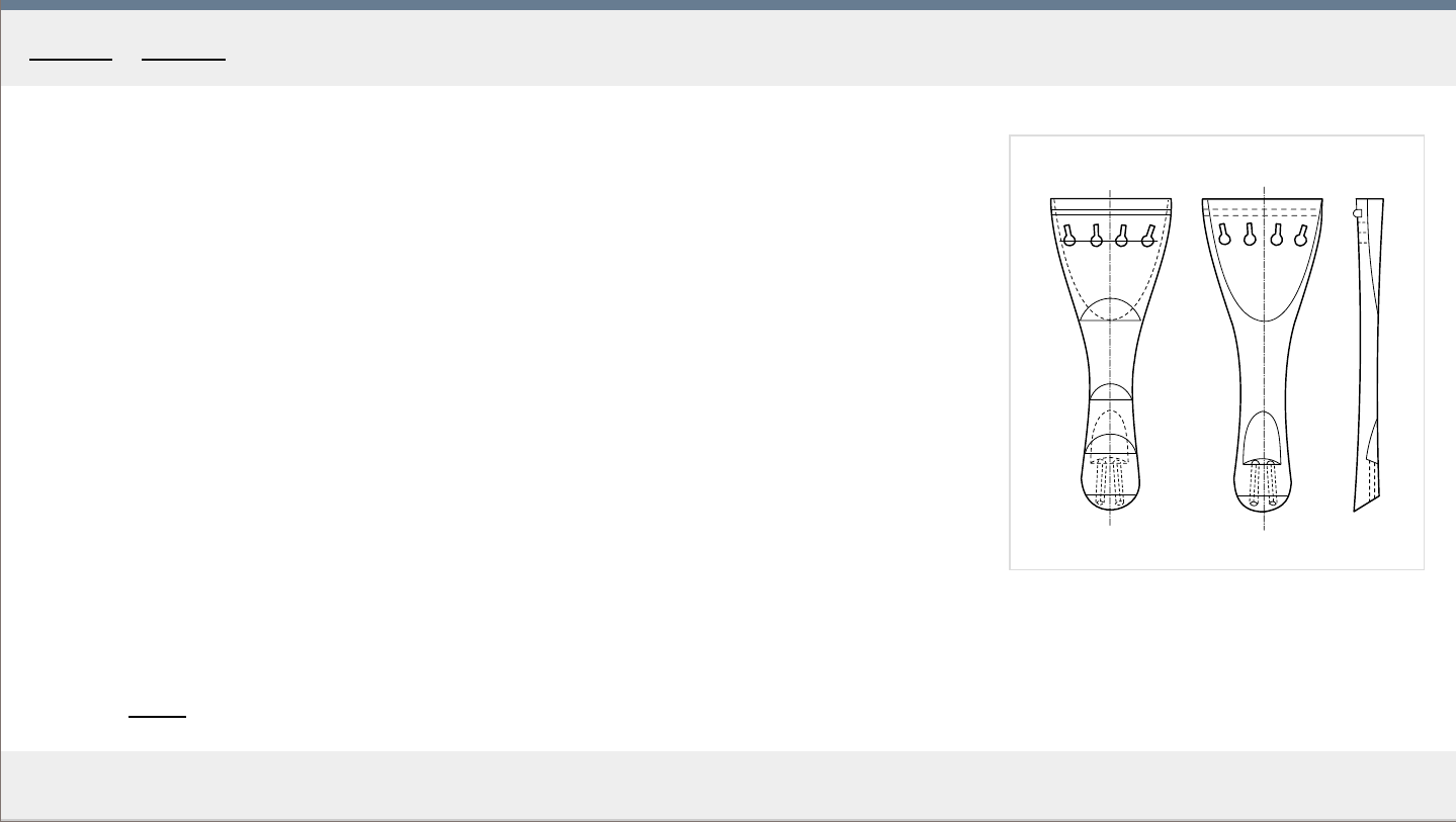
1
MakingTheViolin.com
The tailpiece
The tailpiece can be made of many materials ranging from cheap plastic, aluminium to
rosewood and ebony. With good instruments, quality ebony tailpieces matching ebony pegs
should be used. See Fig. 1 for an example of a tailpiece.
The size of the tailpiece can vary, but properly positioned, the distance from its fret to the top
of the bridge should be around one sixth of the string length from the bridge to the nut.
Most players prefer the fine tuner on the E string only.
Category: Setup
Home - Setup - Tailpiece

MakingTheViolin.com
Stringing up
Stringing up the instrument, start with the G string, followed by the D, A and finally E string.
1
. Make sure that at every turn of the string on the peg is laid down right next to the
pr
evious one. You are progressing towards the pegbox wall.
2. The last turn should end well off the pegbox wall.
3. The E
string is the last to put on, and the first to unwind as it is the most likely to snap.
4. Make sure the bridge stays in its upright position, keep checking and readjusting as you
are winding up the strings. Otherwise it might fall.
5. If you are using tuners, put some cloth underneath them to avoid scratching the varnish
on the top plate.
6. After you have tuned all the strings to correct pitches, let the violin rest for a while and
check back to r
e-tune. Especially with a new violin, as everything is settling down, the
strings will have to be re-tuned a couple of times before they hold the pitch.
Category: Setup
Home - Setup - Strings

MakingTheViolin.com
Setup tips
A] The violin is not responsive enough. When played lightly, it does not sound good. It does
not "want" to be played lightly
.
First lower the pitch. If that helps, consider these:
1. Decrease the string length by moving the bridge forward by say 2mm. This should make
the violin mor
e responsive, but may decrease the overall strength of the tone.
2.
Increased responsiveness can also be got by the decease of tension in the soundpost,
either by moving it a little west, or by shortening it.
3. Increased responsiveness can also be achieved by using thinner strings. As previously
mentioned, all this incr
eased responsiveness costs you the strength in the tone.
B] The violin sounds bland, the sound is too soft, lacking strength.
T
ighten the strings a semitone higher. If it helps, do the opposite of any of the 1,2,3
suggested above, or a combination of them.
If the tone of the violin is lacking carrying power, 1. Increase the distance between the bridge
and the soundpost by moving the soundpost back a little.
Category: Setup
Home - Setup - Resolving problems
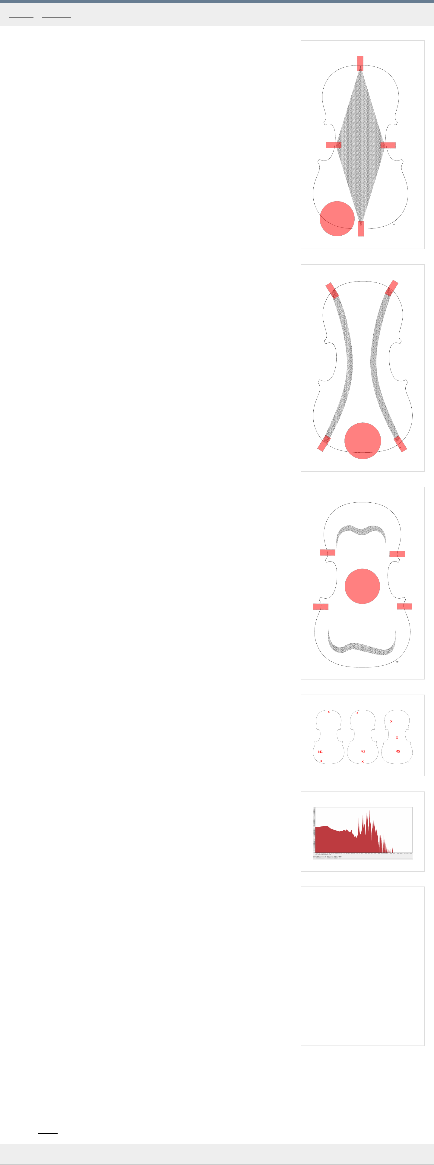
1
M1
2
M2
3
M5
4
5
MakingTheViolin.com
Free plate frequencies
It is difficult to asses the relationship between the resonant frequencies of the free plates and
the plates in an assembled violin. Some makers claim that free plate tuning is for that reason
a waste of time. I think that using the following methods to measure the frequencies of the
free plates as you are working on them can add to your understanding of how the sound
system of the violin works. These methods are not a complete solution in themselves, but
may help you produce, in time, better sounding instruments. With all these, you should keep
a log for every violin you build so that you can refer back to it in case your instrument turns
out to have an exceptionally good tone.
Chladni patterns
The free plates, when excited at certain frequencies, give exceptional responses. These
responses can be visualized with the help of small particles. The vibrational response of the
free plate can spatially be divided in areas with strong response {anti-nodes} and areas with
with little response {nodes}. To get the strongest response possible, the plates should be
fixed at points of as little vibration as possible {nodes} and should get excited in the area of
anti-nodes.
Three frequency responses, or modes M1, M2 and M5 are considered important in violin
plates although a number of other minor modes could be found.
See Fig. 1-3 for M1, M2 and M5 modes Chladni patterns. The red circle is where the driver
{speaker} should be placed. The red rectangles denote the positions of foam patches which
support the plate at the anti-nodes.
The speaker is connected to a power amplifier, which is in turn driven by a sinus signal
generator, ie a PC with tone generator software.
1
. Set up the plate upside down supported by the foam patches, see red r
ectangles in Figs.
2. Place the speaker at the position of the red circle.
3. As the detecting particles use black tea powder extracted from a couple of tea bags.
4. Spread the tea powder evenly on the inner side of the plate.
5. Controlling the tone generator, start a frequency sweep from 400 Hz down. The speed of
the sweep should be maybe 1 Hz per second so that you notice when the plate starts to
r
esonate.
6. First you should reach the M5 frequency. See Fig. 2 for the M5 patter
n.
7. When you see the M5 pattern form, that's the plate's mode 5 frequency.
The same applies for M2 and M1 modes. The M2 should be somewher
e about half of M5 and
M1 could be above half of M2. For best results make sure the speaker is at the sweet spot and
so are the foam pads. The anti-nodes should really have almost no vibrations at all while the
rest should be vibrating strongly.
The patterns presented in Fig. 1-3 are for the back plate and top plate before f-holes are cut
and bassbar added. The top plate with f-holes and bassbar installed generates slightly
different patterns.
Application
So how is this helpful. First, the patterns should be in one word nice. Every plate is different
and the wood varies in density but you should not have patterns that have gaps in them or
are otherwise obviously a result of poor arching or wildly inconsistent wood.
Again, it is a visualization of the frequency response of the whole plate so if you happen to
make a great violin it would be good to know how the patterns looked like.
Second, the patterns can help you locate mode frequencies you may otherwise have a hard
time recognizing, either by ear or in software plots /more on both later/.
Measuring free plate modes by ear
The basic principle is the same here. The speaker is substituted by your knocking finger and
the foam pads by your fingers. So you hold the plate at an anti-node, knock and listen for the
dominant frequency response.
See Fig. 4 to learn where to hold the plates and where to knock. The top positioned "x" is the
spot where you hold the plates, the lower positioned "x" marks the place where to knock.
Application
This serves as a quick method during plate graduation, when you need to keep track of how
the modes keep changing based on where you remove wood.
For most people it is impossible, without any reference, to know what pitch in scale tones or
Herz they are hearing. Here are some methods to reference what you are hearing:
1
. Use a monochord. Knock and then tune the monochord to the pitch you are hearing to get
the fr
equency.
2. Use a chromatic electronic tuner and whistle the pitch you are hearing.
Measuring free plate modes by microphone
The method is identical with the pr
eviously mentioned knocking so refer to Fig. 4 if you need
to. Your ear is supplanted by a microphone and a computer software for analysis. This option
will not only give you the the pitch of the mode but also a whole frequency "image" or plot of
the plate. As this method seems to be the most commonly used today, we will describe it in
some detail.
1
. Download and install Audacity recording software.
2. Connect a microphone.
3. Hold the plate in front of the microphone and record a series of knockings.
4. In Audacity, highlight the sound wave or just the part of it you think is the most
r
epresentative.
5. From top menu choose Analyze> Plot spectrum.
6. A windows shows up where you choose Size > 16384, Axis > Log frequency.
That's it. The plot you see, Fig. 5 is an e
xample, is the graphical interpretation of the plate's
frequency response. The mode you are holding and knocking the plate for should be the
strongest spike in the spectrum. Again M5 should be somewhere between 300-400 Hz, M2
half of M5 and M1 above half of M2.
This works most of the time but sometimes, especially with M1 and M2 it can be quite difficult
to locate. Chladni patterns can help you here.
Humidity
The plate frequencies are bound the the amount of water in the wood. Therefore, you should take your measurements in a stable
environment. Humidity of about 47 percent can be considered ideal.
Category: Tuning
Home - Tuning - F ree plate frequencies
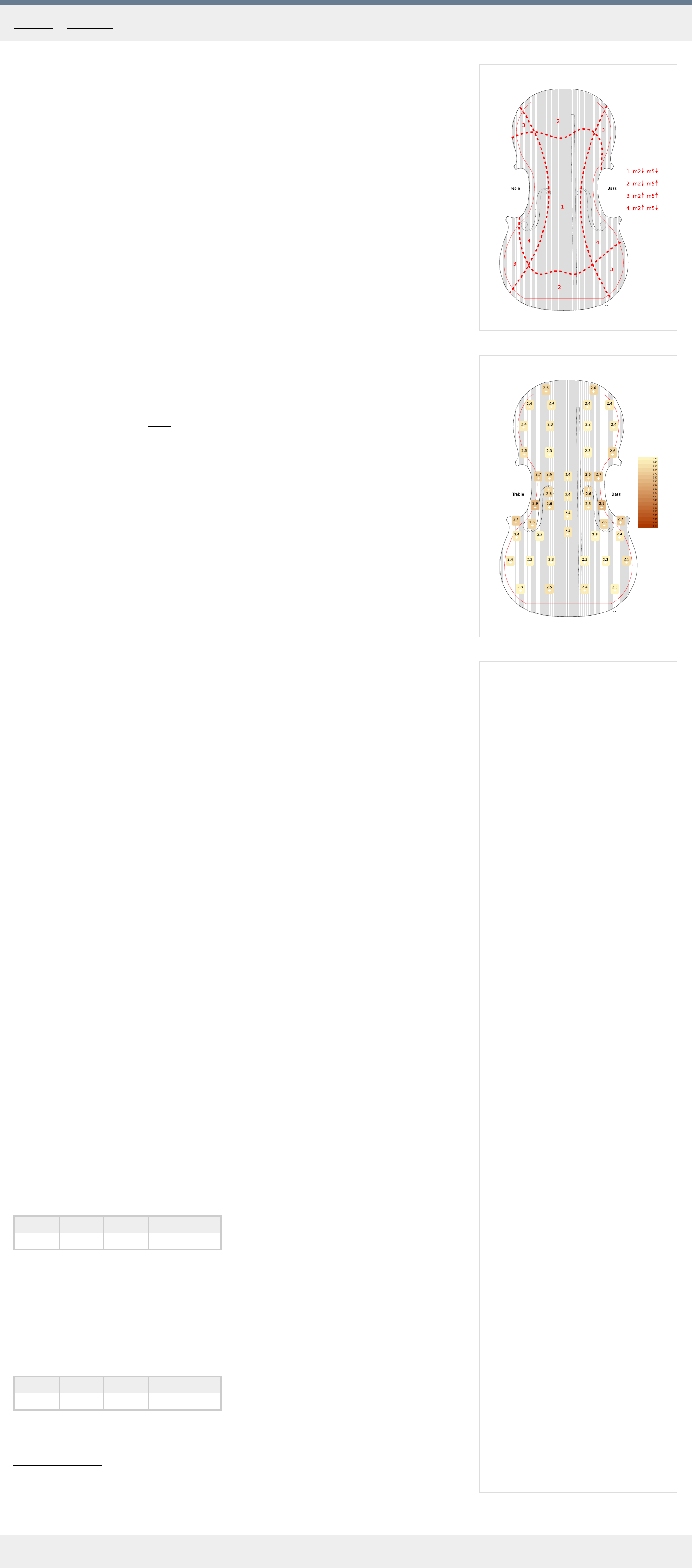
1
2
MakingTheViolin.com
Top plate graduations
Graduations together with arching have a great influence on the resulting tone of the violin.
Graduation patterns
Before you start removing material, you should have an idea what graduation pattern you will
choose.
a) membrane - uniform in thickness all over the plate
b) common - the most used system with the central part thicker
c) reverse - thinner in the center
d) spine - thicker along the center line
Each of these patter
ns has its acoustical qualities, which ideally are matched to the correct
arching. It all depends on what sound you want from the violin.
In our violin we will use the common pattern which is also the pattern Stradivari used in many
of his violins. This pattern is also best if you need to get the M5 frequency as high as possible.
Measuring variables
During graduation you will have to measure the following criteria:
a) Area thickness You will use the thicknessing caliper to measure the thickness in the area
you ar
e working on. See the Tools
section for a description of the thicknessing caliper.
b) Mode frequencies These depend on the stiffness of the plate. The M5 frequency is the
most important. R
efer to the section on plate tuning to learn how to measure these
frequencies.
330-360 Hz here is the accepted range for the common pattern. It shouldn't be more than the
M5 in the back plate.
L
ook at Fig. 1 which describes how areas on a plate affect the mode frequencies. Therefore,
for example, removing material in the central section number 1 lowers both the M5 and M2
frequency.
c) Weight Plate weight influences the ease with which the plate gets e
xcited by the bow. 60-
70 grams range for a finished plate with bassbar often considered is ideal. Too heavy a plate
doesn't resonate freely enough.
d) Flexing Apart from measuring using instruments, you should also get a feel for how the
plate feels in your hands. Fle
x the upper and lower bouts, twist the plate along its axis, flex
the small areas in the bouts.
e) The stiffness index One of the numbers which describe the stiffness, weight and arching
is the stiffness inde
x. It really combines the a) and b) into a formula. The formula is (M5
frequency squared) * weight = stiffness index .
The ideal number for the common pattern is 8 000 000 for the front and 14 000 000 for the
back {bulls eye}.
F
or our finished plate it is (333 squared) * 68 = 7 540 452.
Generally, the goal is to create a plate that is as lightweight as possible, while retaining as
much stiffness as possible.
Thicknesses
In Fig. 2 you see the averages for 48 Stradivari top plates. The thickness maps are here for
reference only so that you have some idea of the real thicknesses. Bear in mind that
Stradivari used first rate wood which allowed him to graduate the plates thinner than you
probably will be able to.
Graduating
Now you know what to check for, so you can start removing material.
1
. Put the plate on something soft so that you don't dent the outside surface.
2. Use a small thumb plane. Make sure you don't remove too much wood in one place. Make
the transitions between ar
eas of different thickness as smooth as possible. Avoid
overthining spots.
3. Keep checking the variables mentioned at the top of the page. First thickness, then
fr
equencies, flexing, weight.
4. Create a table for your measurements, like the one below, to mark your progress.
Plate 4 mm unifor
m thickness:
mode 1 mode 2 mode 5 Plate weight
117 Hz 208 Hz 401 Hz 85 gr
Finishing
1
. When you start getting close to finished, switch to your scraper and finish the surface
smooth.
2. Measure again all variables and make a record.
F
inished plate:
mode 1 mode 2 mode 5 Plate weight
94 Hz 175 Hz 353 Hz 72 gr
The plate is finished for now. The numbers will still change after you have cut out the f-holes
and after the bass bar has been added but not by too much. You can now proceed to the
Cutting the F-holes
.
Category: Tuning
Home - Tuning - Graduations - top plate
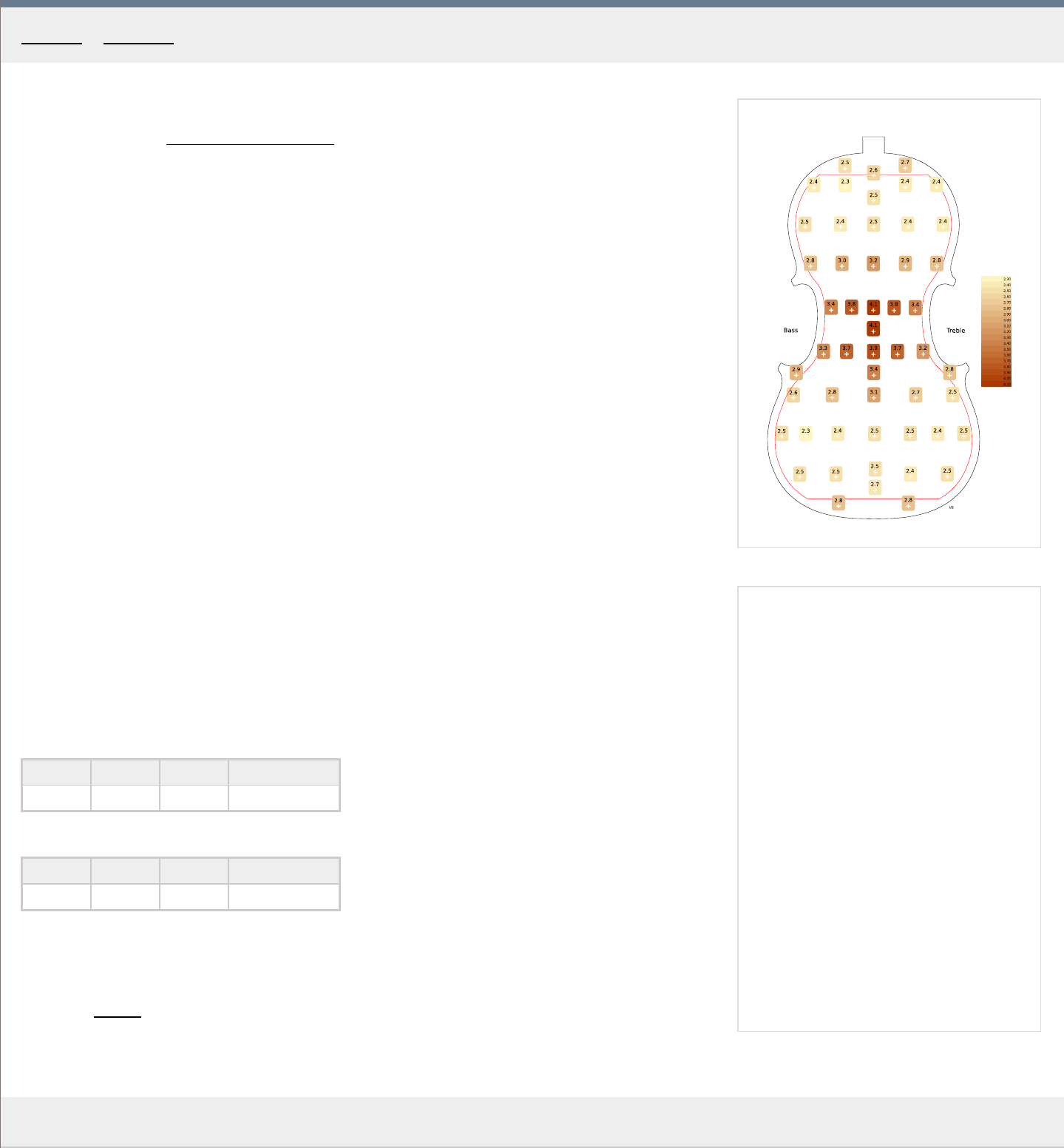
1
MakingTheViolin.com
Back plate graduations
Refer to the section Graduations - top plate
for all the information necessary to asses and
graduate the plates.
Graduation patterns
a) bulls eye - thicker in the center in the for of a circle
b) spine - thicker along the centerline
F
or our violin, we will choose the most common bulls eye pattern. This is also the pattern
Stradivari used, which is obvious from the average thicknesses in his back plates.
Thicknesses
In Fig. 1 you see the averages for 48 Stradivari back plates. You can distinctly see the bulls
eye pattern used here with the thickest part right in the center of the plate. Again, these
figures could be a little thicker. A good rule here is that the thickest part should be twice the
thickness in the bouts.
Graduating
1
. Rest the back on soft material to prevent dents.
2. Use a small thumb plane and start removing wood.
3. Keep checking the M5 frequency and the weight of the plate.
4. Create a table for your measurements, like the one below, to mark your progress.
Starting plate:
mode 1
mode 2 mode 5 Plate weight
* Hz * Hz 430 Hz 143 gr
F
inished plate:
mode 1 mode 2 mode 5 Plate weight
* Hz * Hz 364 Hz 107 gr
Stiffness inde
x: 14 177 072
(364 squared) * 107 = 14 177 072
Category: Tuning
Home - Tuning - Graduations - back plate

MakingTheViolin.com
Measurements of the Antonio Stradivari 'Messiah' 1716 violin, in millimeters
Back Belly Misc
LENGTH taken from the side of the button 356 356
Upper bouts 167.5 167
Middle bouts, taken at the narrowest point 108.3 108.9
Lower bouts 208 207.5
Arching height, across arch, includes averaged edge
thickness
15.4 13.8
Stop length bass 196.5 treble 195
Corner width
upper 6.7-
6.9
lower 7.0-7.2
Purfling distance from edge 3.75
Purfling width white 0.6 black 0.4 total 1.4
Purfling depth back only bouts 1.1-1.2 corners 0.8-1
Overhang bouts 2.4-6
corners 1.8-
2.3
Button height 14.5 width 17.1
thickness
3.8
String length 328.5
Neck length 129
Average Measurements of the V iolin in millimeters
1/4 1/2 3/4 7/8 4/4
CORPUS length 285 320 335 345 355
width
upper bout ca. 133 145 156 162 168
middle bout ca. 91 97 105 109 112
lower bout ca. 163 182 195 200 206
SCROLL length ca. 85 94 101 104 108
RIBS height - uniform 26 28 29 29.5 30
thickness ca. 1.0 1.0 1.1 1.1 1.1
MOLD thickness 12
LININGS thickness 1.5 1.5 1.5 1.7 1.8
width 4 5 5 6 6
BLOCKS size upper 41/13 44/13 47/14 48/14 50/15
lower 36/12 39/12 42/13 43/13 45/14
upper corners 14/7 15/8 15/8 16/9 22/10
lower corners 16/8 17/9 17/9 18/10 21/11
ARCHING HEIGHT back ca. 13.2 13.7 14.1 14.3 14.5
belly ca. 13.7 14.3 14.9 15.2 15.5
BACK average thickness at: sound post 3.2 3.5 3.9 4.1 4.3
upper and lower bouts 2 2 2.2 2.3 2.5
sinking (in general) 1.8 1.8 2 2.1 2.3
sinking at center bout 2 2 2.2 2.3 2.5
edges 3.1 3.2 3.4 3.7 3.8
BELLY average thickness at: sound post 2.5 2.5 2.8 2.9 3
upper and lower bouts 2.2 2.2 2.4 2.5 2.7
sinking (in general) 2 2 2.1 2.3 2.4
sinking at center bout 2.3 2.4 2.4 2.6 2.7
edges 3.2 3.3 3.5 3.9 4
EDGES overhang from ribs 2.2
CORNERS width 7 - 7.5
thickness, back ca. 4
thickness, belly ca. 4.2
PURFLING distance from edge ca. 3 3.1 3.2 3.3 3.5-3.8
width ca. 1.1 1.1 1.1 1.1 1.2
FF-HOLES length between ends of wings 62 68 71 73 75
between upper eyes 35 36 38 41 42
lower eye to edge 10 10 11 11.5 12
MENSUR: 2:3 proportion belly 159 171 183 189 195
neck to edge 106 114 122 126 130
addition for mortise 6
BASSBAR after fitting length ca. 215 240 255 267 276
thickness ca. 4 4 4.5 5 5.5
height at center ca. 8 9 10 11 12
FINGERBOARD length 215 238 255 262 270
underside hollowing 60 70 78 90 100
width at nut 20 21 22 23.5 24
width at bridge end 35 38 40 42 43
radius of curve 32 35 38 39.5 41.5
thickness: end of neck 7 7 8 8.5 9
thickness:edges 4 4.5 5 5 5.5
projection (at bridge) 27
ht over belly at bridge end 16.5 17 19.5 20 21
string angle at bridge 156° 156° 157° 157° 158°
NUT thickness 4 4.5 5 5 5.5
SCROLL width at eyes 42
PEGBOX width at nut see fingerboard width
width at throat 14 15 16.5 18 19.5
length ca. 60 65 68 72 72-76
thickness of walls 5.5
PEGS distance a - g 40 46 50 53 55
e - d 12 13 14 15 16
protrusion, pegbox to collar 9 10 10 11 12
NECK, foot overstand* 5.5 6 6 6.5 6.5
angle 87° 87° 87° 87° 87°
thickness including fingerboard 15/17 16/18 17/19 18/20 19/21
BUTTON width 17 19 20 21 21
height 10 11 11.5 12 12
SADDLE length 32 33 34 35 36
STRINGS spacing at nut 13 13.5 15 16 16.5
spacing at bridge 26 28 31 33 34
vibrating length: nut to bridge 267 287 307 317 328
height over end of fingerboard steel/gut
e 2.5/3.0
g 4/4.5
SOUNDPOST thickness ca. 4 4.5 5 5.5 6
BRIDGE width at feet 32 37 38 41 42
thickness 4.5
height ca. 30 30 32 32 33
Home - Measurements
